Hand tools are often neglected in the search for the pleasing objects of the past. Considered too utilitarian, their decorative appeal—the mellow patina of the wood plane or the delicately tapered legs of a pair of dividers—often goes unnoticed. Surprisingly modern in design, the ancient carpenter’s or cabinetmaker’s tool has a vitality of line that can, without reference to technical significance, make it an object of considerable grace and beauty. The hand tool is frequently a lively and decorative symbol of a society at a given time—a symbol, which, according to the judges at London’s Crystal Palace Exhibition in 1851, gives “indications of the peculiar condition and habits of the people whence they come, of their social and industrial wants and aims, as well as their natural or acquired advantages.”[8] The hand tool, therefore, should be considered both as an object of appealing shape and a document illustrative of society and its progress.
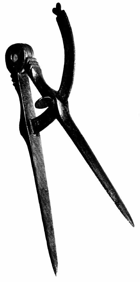 Figure 15.—18th century: Cabinetmaker’s dividers of English origin. (Private collection. Smithsonian photo 49789-B.)
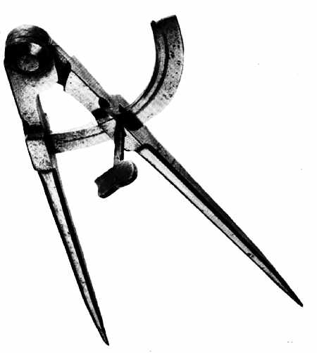 Figure 16.—1783: Cabinetmaker’s dividers of English manufacture, dated, and marked T. Pearmain. See detail, figure 17. (Smithsonian photo 49792-C.)
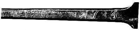 Figure 17.—1783: Detail of cabinetmaker’s dividers showing name and date.
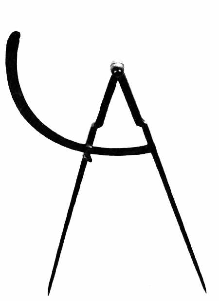 Figure 18.—18th century: Carpenter’s dividers of English origin, undated. (Smithsonian photo 49792-B.)
On first sight, it is the conformation rather than any facet of its technical or social significance that strikes the eye; perhaps the most decorative of tools are early dividers and calipers which, prior to their standardization, existed in seemingly endless variety. The great dividers used by the shipbuilder and architect for scribing and measuring timbers not only indicate building techniques (accession 61.548) but also document 17th-and early 18th-century decorative metalwork, as seen in figure 13. Well before the 17th century, artists and engravers recognized them as intriguing shapes to include in any potpourri of instruments, either in cartouches or the frontispieces of books (fig. 14).
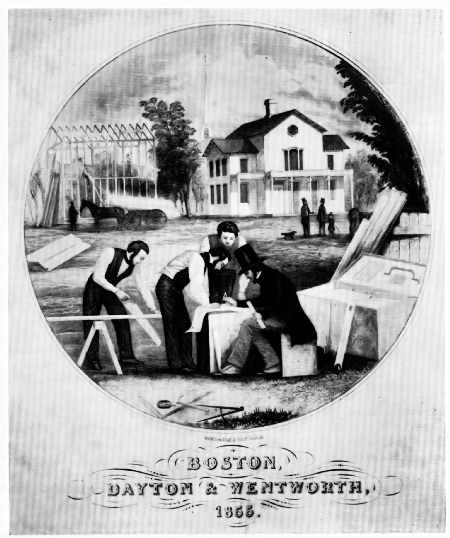 Figure 19.—1855: The frontispiece from Edward Shaw, The Modern Architect (Boston, 1855), shows the carpenter’s dividers in the foreground unchanged in form from those illustrated in figure 18. Of further interest in Shaw’s plate is the dress of the workmen and the balloon frame of the house under construction. (Smithsonian photo 49792-A.)
The two pairs of cabinetmaker’s dividers illustrated in figures 15 and 16 suggest significant changes in the design of a basic tool. The dividers shown in figure 15 are English and would seem to be of early 18th-century origin, perhaps even earlier. They are Renaissance in feeling with decorated legs and a heart-shaped stop on the end of the slide-arm. In character, they are like the great dividers shown in figure 13: functional, but at the same time preserving in their decoration the features common to a wide variety of ironwork and wares beyond the realm of tools alone. The dividers pictured in figure 16 are a decided contrast. Dated 1783, they are strongly suggestive of Sheffield origin. Gone is the superfluous decoration; in its place is the strong, crisp line of a tool that has reached nearly the ultimate of function and manufacture, a device which both in general appearance and precise design is very modern in execution. Equally intriguing are the smaller, more slender dividers (accession 319557) of the 18th-century house-builder as seen in figure 18, a form that changed very little, if at all, until after 1850—a fact confirmed by the frontispiece of Edward Shaw’s The Modern Architect, published in Boston in 1855 (fig. 19). The double calipers of the woodturner (fig. 20) have by far the most appealing and ingenious design of all such devices. Designed for convenience, few tools illustrate better the aesthetic of the purely functional than this pair of 19th-century American calipers.
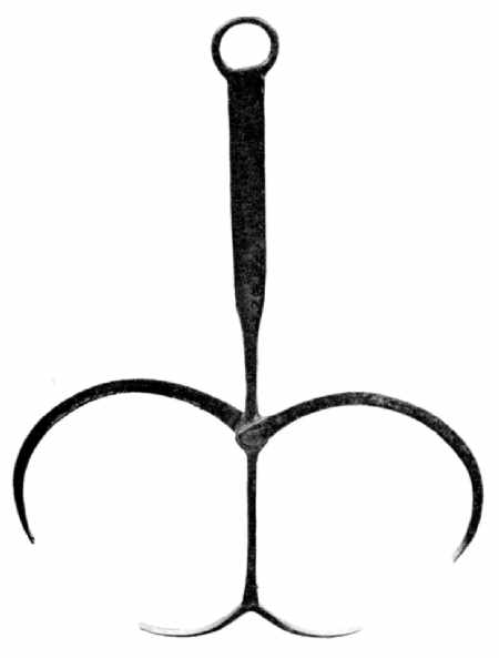 Figure 20.—Early 19th century: The double calipers of the woodturner permitted double readings to be taken without changing the set of the tool. Inherent in this practical design is a gracefulness of line seldom surpassed. (Private collection. Smithsonian photo 49793-C.)
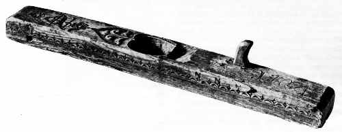 Figure 21.—1704: The floor plane or long joiner of Norwegian origin exhibits the characteristic decoration of the stock and mouth, patterns common on tools of northern European and Scandinavian origin. (Courtesy of the Norsk Folkemuseum, Oslo, Norway.)
Intended to establish proportion and to insure precision, it seems a natural consequence that dividers and calipers should in themselves reflect the same sense of balance and grace that they were designed to govern. Still, even the most prosaic examples of woodworking tools, completely divorced from the quasi-mathematical devices of measure and proportion, have this quality and can be admired solely as decorative objects. This is most evident in the three European bench planes illustrated in figures 21, 22, and 23: one Norwegian, dated 1704; one Dutch (accession 319562), dated 1756; and one German, dated 1809. The Norwegian and German examples, with their elaborately carved bodies and heart-shaped mouths, are typical of the type that Swedish and German colonists in America might have used in the 17th and 18th centuries. They are important for that reason. Also, all three exhibit elaboration found on other material survivals from these countries in their respective periods. For example, the incised rosette of the Dutch plane (fig. 22) is especially suggestive of the rosettes found on English and American furniture of the 1750’s and 1760’s, specifically on high chests.
The decorative motifs that characterized European tools of the 17th and 18th centuries obscured technical improvement. By contrast, in England and America, tools gained distinction through the directness of their design. Following English patterns, tools of American make were straightforward. Only later, in new tool types, did they imitate the rococo flourish of their European predecessors. In America, as in England, the baroque for things functional seemingly had little appeal. This is particularly true of woodworking planes on which, unlike their continental cousins, embellishment is rarely seen. Exemplifying this tradition are three early 19th-century American planes: a plow, for cutting channels of various widths on board edges, marked “G. White, Philda” (fig. 24); a rabbet, for notching the margin of boards; made by E.W. Carpenter of Lancaster, Pennsylvania (fig. 25); and a jack or foreplane, for rough surfacing (accession 61.547), made by A. Klock and dated 1818 as seen in figure 26.
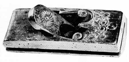 Figure 22.—1756: The highly elaborated stock and rosette-incised wedge of the smoothing plane recall the decoration on furniture of the period. The plane is of Dutch origin. (Smithsonian photo 49792-F.)
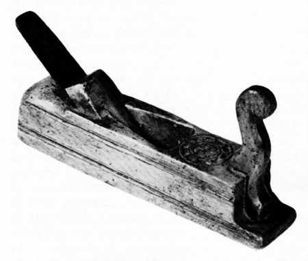 Figure 23.—1809: This bench plane of German origin is dated 1809. It is of a traditional form that persists to the present day. The planes pictured in figures 21, 22, and 23 are similar to the type brought to North America by non-English colonists. (Private collection. Smithsonian photo 49793-F.)
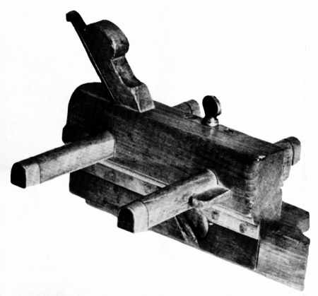 Figure 24.—About 1818: This plow plane, used to cut narrow channels on the edges of boards, was made by G. White of Philadelphia in the early 19th century. It is essentially the same tool depicted in the catalogues of Sheffield manufactures and in the plates from Martin and Nicholson. The pattern of the basic bench tools used in America consistently followed British design, at least until the last quarter of the 19th century. (Private collection. Smithsonian photo 49794-E.)
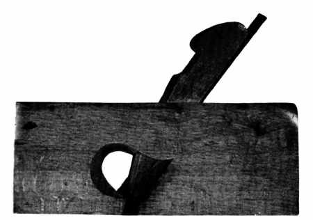 Figure 25. 1830–1840: The design of the rabbet plane, used to cut a groove of fixed width and depth on the edge of a board, was not improved upon in the 19th century. The carpenter’s dependence on this tool lessened only after the perfection of multipurpose metallic planes that could be readily converted to cut a “rabbet.” (Private collection. Smithsonian photo 494789-H).
The question of dating arises, since only the Klock piece is firmly fixed. How, for example, is the early 19th-century attribution arrived at for the planes inscribed White and Carpenter? First, the nature of the stamped name “G. White” is of proper character for the period. Second, G. White is listed in the Philadelphia city directories as a “plane-maker” between the years 1818 and 1820, working at the back of 5 Filbert Street and later at 34 Juliana Street. Third, internal evidence on the plane itself gives a clue. In this case, the hardware—rivets and furrels—is similar if not identical to that found on firearms of the period, weapons whose dates of manufacture are known. The decorative molding on the fence of this plane is proper for the period; this is not a reliable guide, however, since similar moldings are retained throughout the century. Finally, the plane is equipped with a fence controlled by slide-arms, fixed with wedges and not by adjustable screw arms. After 1830, tools of high quality, such as White’s, invariably have the screw arms. The rabbet plane, made by Carpenter, is traceable via another route, the U.S. Patent Office records. Carpenter, self-designated “toolmaker of Lancaster,” submitted patents for the improvement of wood planes between 1831 and 1849. Examples of Carpenter’s work, always stamped as shown in figure 27, survive, both dated and undated. There are several of his planes in the collections of the Bucks County Historical Society, and dated pieces are known in private collections.
Inherent in the bench planes is a feeling of motion, particularly in the plow and the rabbet where basic design alone conveys the idea that they were meant to move over fixed surfaces. Of the three examples, only the brass tippings and setscrew of the plow plane suggest any enrichment, and of course these were not intended for decoration; in later years, however, boxwood, fruitwood, and even ivory tips were added to the more expensive factory models. Also unintentional, but pleasing, is the distinctive throat of the rabbet plane—a design that developed to permit easy discharge of shavings, and one that mass manufacture did not destroy.
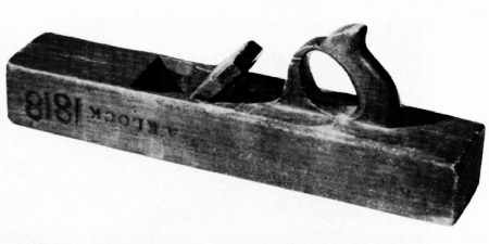 Figure 26.—1818: The jack plane, used first by the carpenter for rapid surfacing, is distinguished primarily by the bezeled and slightly convex edge of its cutting iron. As with the plow and the rabbet, its shape is ubiquitous. Dated and marked A. Klock, this American example follows precisely those detailed in Sheffield pattern books. (Smithsonian photo 49794-C.)
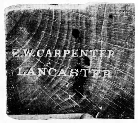 Figure 27.—1830–1840: Detail of the rabbet plane (fig. 25) showing the characteristic stamp of E.W. Carpenter. (Smithsonian photo 49794-D.)
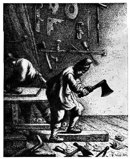 Figure 28.—About 1631: The preceding illustrations emphasize the divergent appearance of European and Anglo-American tools. This, however, was not always the case. The woodworker’s shop by the Dutch engraver Jan Van Vliet suggests the similarity between English and European tool types in the 17th century. Note in particular the planes, axe, brace, and auger as compared to Moxon. (Library of Congress, Division of Prints and Photographs.)
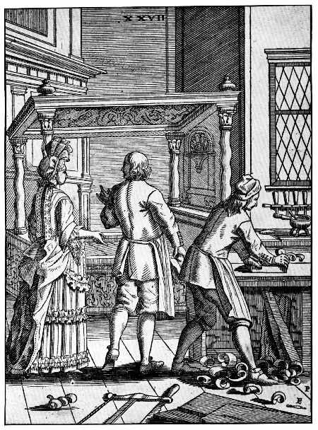 Figure 29.—1690: The cabinetmaker’s shop from Elias Pozelius, Orbus Pictus nach Zeichnugen der Susanna Maria Sandrart, Nürnberg, 1690. (Library of Congress.)
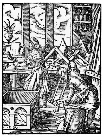 Figure 30.—1568: The woodworker’s shop from Hans Sachs, Eygentliche Beschrerbung Aller Stande … mit Kunstreichen Figuren [by Jost Amman], Frankfurt, 1568. (Library of Congress.)
The divergence from European to an Anglo-American hand-tool design and the approximate date that it occurred can be suggested by a comparison of contemporary illustrations. The change in the wooden bench plane can be followed from the early 17th century through its standardization at the end of the 18th century. Examine first the planes as drawn in the 1630’s by the Dutchman Jan Van Vliet (fig. 28), an etcher of Rembrandt’s school at Leiden, and also the examples illustrated by Porzelius (fig. 29) and by Jost Amman (fig. 30). Compare them to Moxon’s plate (fig. 31) from the Mechanick Exercises (3rd ed., 1703) and to the splendid drawing of the bench plane from André-Jacob Roubo’s L’Art du menuisier, published in 1769 (fig. 32). In all of them, the rounded handle, or tote, and the fore-horn appear, characteristics of both European and English planes of the period before 1750. The similarity ends with the mass production of hand tools from the shops of the English toolmaking centers, principally Sheffield. An illustration from a pattern and design book of the Castle Hill Works, Sheffield, dating from the last quarter of the 18th century (fig. 33), shows the achieved, familiar form of the bench planes, as well as other tools. The use of this form in America is readily documented in Lewis Miller’s self-portrait while working at his trade in York, Pennsylvania, in 1810 (fig. 34) and by the shop sign carved by Isaac Fowle in 1820 for John Bradford (fig. 35). In each example, the bench plane clearly follows the English prototype.
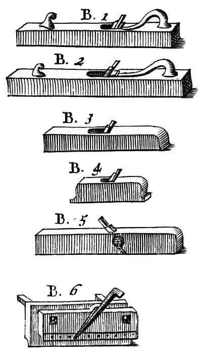 Figure 31.—1703: Detail of the bench planes from Moxon’s Mechanick Exercises.
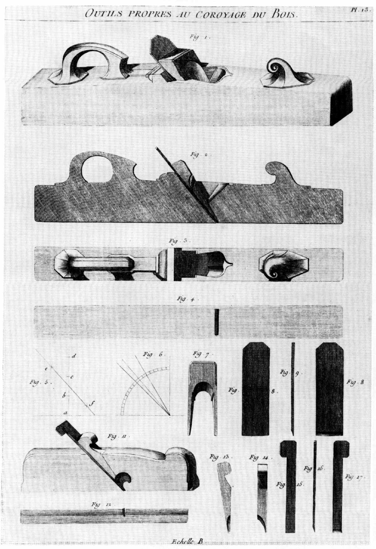 Figure 32.—1769: André-Jacob Roubo’s precise rendering of the bench plane retains the essential features shown by Moxon—the rounded tote or handle and the curved fore-horn. (André-Jacob Roubo, L’Art du menuisier, 1769.)
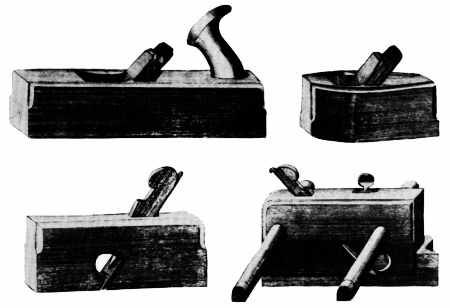 Figure 33.—Early 19th century: The bench plane illustrated in Roubo or Moxon is seldom seen in American tool collections. The bench planes, smoothing planes, rabbets, and plows universally resemble those shown in this illustration from the pattern book of the Castle Hill Works, Sheffield. (Book 87, Cutler and Company, Castle Hill Works, Sheffield. Courtesy of the Victoria and Albert Museum.)
 Figure 34.—About 1810: Lewis Miller working at his bench in York, Pa. In a predominantly Pennsylvania-German settlement, the plane used by Miller conforms to the Sheffield type illustrated in the catalogue of the Castle Hill Works as shown in figure 33. (York County Historical Society, York, Pa.)
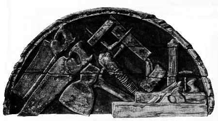 Figure 35.—1820: John Bradford’s shop sign carved by Isaac Fowle is a unique documentary of early 19th-century tool shapes and is in the Bostonian Society, Boston, Mass. (Index of American Design, The National Gallery, Washington, D.C.)
 Figure 36.—1703: The joiner’s brace and bit—a detail from Moxon, Mechanick Exercises …, London, 1703. (Library of Congress, Smithsonian photo 56635.)
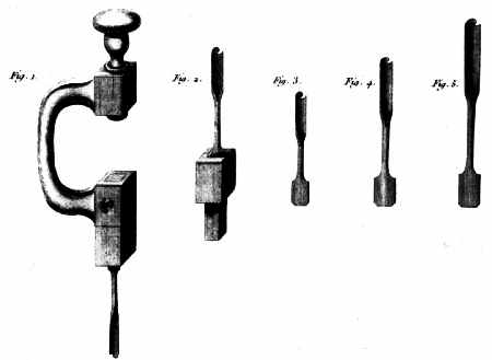 Figure 37.—1769: Roubo’s illustration of the brace and bit differs from Moxon’s only in the precision of the delineation. Contrast this form with that of the standard Sheffield version in figure 38 and the metallic braces illustrated in figures 40 through 44. From these plates can be seen the progression of the bitstock toward its ultimate perfection in the late 19th century. (André-Jacob Roubo, L’Art du menuisier, 1769.)
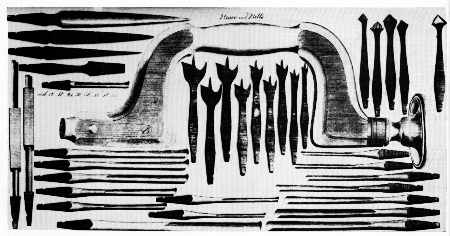 Figure 38.—Early 19th century: The mass-produced version of the wooden brace and bit took the form illustrated in Book 87 of Cutler’s Castle Hill Works. (Courtesy of the Victoria and Albert Museum.)
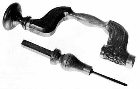 Figure 39.—18th century: The transitional form of the wooden brace and bit incorporated the overall shape of the mass-produced version but retained the archaic method of fastening the bit to the chuck. The tool is of Dutch origin and suggests the influence of Sheffield design on European tools. (Smithsonian photo 49792-E.)
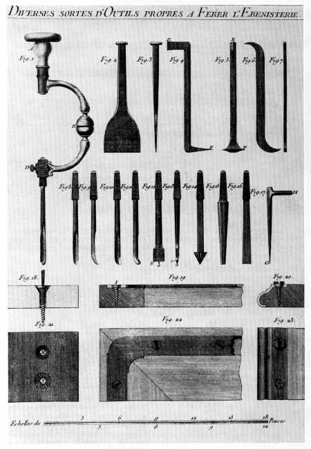 Figure 40.—1769: Roubo illustrated the metallic brace and, in addition, suggested its use as a screwdriver. (André-Jacob Roubo, L’Art du menuisier,1769.)
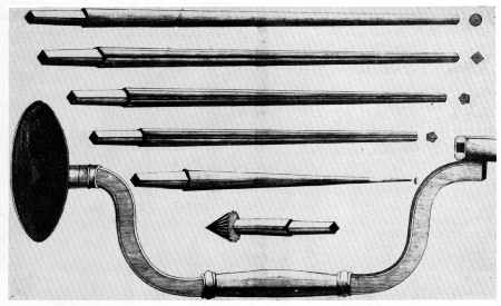 Figure 41.—About 1775: Ford, Whitmore and Brunton made and sold clockmaker’s braces of metal with a sweep and shank that was imitated by American patentees in the 19th century. (Catalogue of Ford, Whitmore and Brunton, Birmingham, England. Courtesy of the Birmingham Reference Library.)
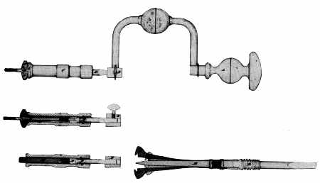 Figure 42.—1852: Nearly one hundred years after Roubo’s plate appeared, Jacob Switzer applied for a patent for an “Improved Self Holding Screw Driver.” The similarity of Switzer’s drawing and Roubo’s plate is striking. (Original patent drawing 9,457, U.S. Patent Office, Record Group 241, the National Archives.)
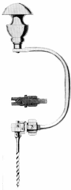 Figure 43.—1866: The simplicity and strength of the brace proposed by J. Parker Gordon is in sharp contrast to the heavily splinted sides of the wooden brace commonly used in mid-19th-century America. (Original patent drawing 52,042, U.S. Patent Office, Record Group 241, the National Archives.)
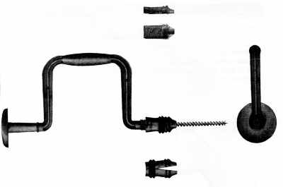 Figure 44.—1865: Milton nobles’ patent perfecting the chuck which held the auger bit was an important step along the path which led ultimately to the complete acceptance of the metallic brace. Barber’s ratchet brace shown in figure 66 completes the metamorphosis of this tool form in the United States. (Original patent drawing 51,660, U.S. Patent Office, Record Group 241, the National Archives.)
The carpenter’s brace is another instance of divergent design after a common origin. Refer again to Van Vliet’s etching of the woodworker’s shop (fig. 28), to the detail from Moxon (fig. 36), and from Roubo (fig. 37). All show the brace in a form familiar since the Middle Ages, a shape common to both delineators and craftsmen of the Continent and the British Isles. But, as the plane changed, so changed the brace. The standard form of this tool as it was used and produced in the United States in the 19th century can be seen in another plate from the catalogue of the Castle Hill Works at Sheffield (fig. 38). This English influence on American tool design is no surprise, since as early as 1634 William Wood in New England’s Prospect suggested that colonists take to the New World “All manner of Ironwares, as all manner of nailes for houses … with Axes both broad and pitching … All manners of Augers, piercing bits, Whip-saws, Two handed saws, Froes …, rings for Bettle heads, and Iron-wedges.”
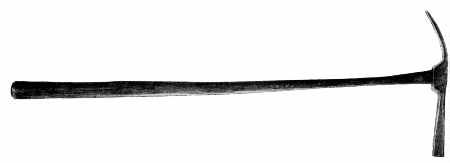 Figure 45.—19th century: The upholsterer’s hammer is an unknown; it is not dated, its maker is anonymous, as is its user. It is of American origin, yet of a style that might have been used in England or on the Continent. This lack of provenance need not detract from its significance as a material survival. This hammer, the brace (fig. 46), the bevel (fig. 47), and the compass saw (fig. 48) are sufficiently provocative in their design to conjure some image of a technology dependent upon the skilled hand of craftsmen working in wood and of the relationship between the hand, the tool, and the finished product. (Smithsonian photo 49793-A.)
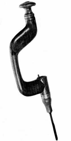 Figure 46.—18th century: The brace and bit in its nonfactory form conforms to a general design pattern in which none of the components are ever precisely alike. This aspect of variety of detail—sophistication, crudeness, decorative qualities or the like—reflects something of the individuality of the toolmaker, a quality completely lost in the standardization of the carpenter’s brace. (Smithsonian photo 49794-A.)
English tool design in the 18th century also influenced the continental toolmakers. This can be seen in figure 39 in a transitional-type bitstock (accession 319556) from the Low Countries. Adopting an English shape, but still preserving the ancient lever device for holding the bit in place, the piece with its grapevine embellishment is a marked contrast to the severely functional brass chucks on braces of English manufacture. No less a contrast are metallic versions of the brace. These begin to appear with some regularity in the U.S. patent specifications of the 1840’s; their design is apparently derived from 18th-century precedents. Roubo (fig. 40) illustrated a metal bitstock in 1769, as did Ford, Whitmore & Brunton, makers of jewelers’ and watchmakers’ tools, of Birmingham, England, in their trade catalogue of 1775 (fig. 41). Each suggests a prototype of the patented forms of the 1840’s. For example, in 1852, Jacob Switzer of Basil, Ohio, suggested, as had Roubo a hundred years earlier, that the bitstock be used as a screwdriver (fig. 42); but far more interesting than Switzer’s idea was his delineation of the brace itself, which he described as “an ordinary brace and bit stock” (U.S. pat. 9,457). The inference is that such a tool form was already a familiar one among the woodworking trades in the United States. Disregarding the screwdriver attachment, which is not without merit, Switzer’s stock represents an accurate rendering of what was then a well-known form if not as yet a rival of the older wooden brace. Likewise, J. Parker Gordon’s patent 52,042 of 1866 exemplifies the strengthening of a basic tool by the use of iron (fig. 43) and, as a result, the achievement of an even greater functionalism in design. The complete break with the medieval, however, is seen in a drawing submitted to the Commissioner of Patents in 1865 (pat. 51,660) by Milton V. Nobles of Rochester, New York.[9] Nobles’ creation was of thoroughly modern design and appearance in which, unlike earlier types, the bit was held in place by a solid socket, split sleeve, and a tightening ring (fig. 44). In three centuries, three distinct design changes occurred in the carpenter’s brace. First, about 1750, the so-called English or Sheffield bitstock appeared. This was followed in the very early 19th century by the reinforced English type whose sides were splinted by brass strips. Not only had the medieval form largely disappeared by the end of the 18th century, but so had the ancient lever-wedge method of fastening the bit in the stock, a device replaced by the pressure-spring button on the side of the chuck. Finally, in this evolution, came the metallic stock, not widely used in America until after the Civil War, that embodied in its design the influence of mass manufacture and in its several early versions all of the features of the modern brace and bit.
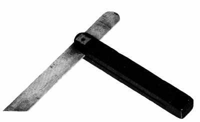 Figure 47.—18th century: The visually pleasing qualities of walnut and brass provide a level of response to this joiner’s bevel quite apart from its technical significance. (Private collection. Smithsonian photo 49793-B.)
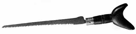 Figure 48.—18th century: The handle of the compass saw, characteristically Dutch in shape, is an outstanding example of a recurring functional design, one which varied according to the hand of the sawer. (Smithsonian photo 49789-C.)
Henry Ward Beecher, impressed by the growing sophistication of the toolmakers, described the hand tool in a most realistic and objective manner as an “extension of a man’s hand.” The antiquarian, attuned to more subjective and romantic appraisals, will find this hardly sufficient. Look at the upholsterer’s hammer (accession 61.35) seen in figure 45: there is no question that it is a response to a demanding task that required an efficient and not too forceful extension of the workman’s hand. But there is another response to this implement: namely, the admiration for an unknown toolmaker who combined in an elementary striking tool a hammerhead of well-weighted proportion to be wielded gently through the medium of an extremely delicate handle. In short, here is an object about whose provenance one need know very little in order to enjoy it aesthetically. In a like manner, the 18th-century bitstock of Flemish origin (fig. 46), the English cabinetmaker’s bevel of the same century (fig. 47), and the compass saw (accession 61.52, fig. 48) capture in their basic design something beyond the functional extension of the craftsman’s hand. The slow curve of the bitstock, never identical from one early example to another, is lost in later factory-made versions; so too, with the coming of cheap steel, does the combination of wood (walnut) and brass used in the cabinetmaker’s bevel slowly disappear; and, finally, in the custom-fitted pistol-like grip of the saw, there is an identity, in feeling at least, between craftsman and tool never quite achieved in later mass-produced versions.
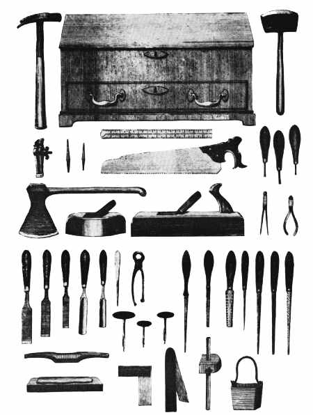 Figure 49.—Early 19th century: The designation “gentleman’s tool chest” required a chest of “high-style” but necessitated no change in the tools it held. (Book 87, Cutler and Company, Castle Hill Works, Sheffield. Courtesy of the Victoria and Albert Museum.)
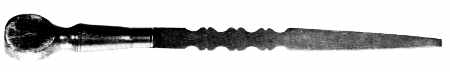 Figure 50.—19th century: The screwdriver, which began to appear regularly on the woodworker’s bench after 1800, did not share the long evolution and tradition of other Anglo-American tool designs. The screwdriver in its early versions frequently had a scalloped blade for no other purpose than decoration. (Smithsonian photo 49794.)
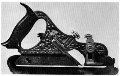 Figure 51.—1870: The use of a new material prompted a departure from the traditional in shape and encouraged surface elaboration. The tendency, however, was short lived and the mass-produced metallic plane rapidly achieved a purity of design as pleasing as its wooden predecessors. (Private collection. Smithsonian photo 49789.)
Occasionally, ruling taste is reflected in the design of the carpenter’s equipment. Notable is the “gentleman’s tool chest” (fig. 49) advertised in the pattern book of the Castle Hill Works. The bracket feet, brass pulls, and inlaid keyholes imitate the style of the domestic chest of drawers of the period 1790 to 1810—undoubtedly, features included by the manufacturer to appeal to a gentleman of refined taste. In contrast to this Sheffield product is the plate from Shaw’s The Modern Architect. The concept of the builder-carpenter as a gentleman still prevails, although the idea in this American scene is conveyed in the mid-19th century through fashionable dress. The tools and in particular the tool chest reflect only the severest of functional lines (fig. 19, p. 196).
In deference to ruling taste, some tools lost for a time the clean lines that had long distinguished them. The screwdriver, simple in shape (accession 61.46) but in little demand until the 1840’s, occasionally became most elaborate in its factory-made form (fig. 50) and departed noticeably from the unadorned style of traditional English and American tools. The scalloped blade, influenced by the rival styles rather than a technical need, seemed little related to the purpose of the tool.[10] No less archaic in decoration was the iron-bodied version of the plow plane (fig. 51). The Anglo-American tradition seems completely put aside. In its place is a most functional object, but one elaborately covered with a shell and vine motif! Patented in 1870 by Charles Miller and manufactured by the Stanley Rule and Level Company, this tool in its unadorned version is of a type that was much admired by the British experts at Philadelphia’s Centennial Exhibition in 1876. What prompted such superfluous decoration on the plow plane? Perhaps it was to appeal to the flood of newly arrived American craftsmen who might find in the rococo something reminiscent of the older tools they had known in Europe. Perhaps it was simply the transference to the tool itself of the decorative work then demanded of the wood craftsmen. Or was it mainly a compulsion to dress, with little effort, a lackluster material that seemed stark and cold to Victorians accustomed to the ornateness being achieved elsewhere with the jigsaw and wood? Whatever the cause, the result did not persist long as a guide to hand-tool design. Instead, the strong, plain lines that had evolved over two centuries won universal endorsement at the Centennial Exhibition. The prize tools reflected little of the ornateness apparent in the wares of most of the other exhibitors. American makers of edge tools exhibiting at the Centennial showed the world not only examples of quality but of attractiveness as well.
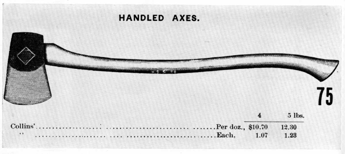 Figure 52.—19th century: The American axe was unexcelled in design and ease of use. European observers praised it as distinctly American. At the Centennial Exhibition in 1876 Collins and Company of New York City was singled out as one of the outstanding manufacturers exhibiting these axes, a reputation that persisted. (Tools for all Trades, Hammacher, Schlemmer and Company, New York, 1896. Smithsonian photo 56625.)
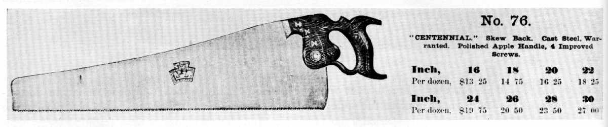 Figure 53.—1876: Disston and Sons long continued to remind prospective buyers of the company’s success at the Philadelphia Centennial Exhibition by retaining the “Centennial Saw, No. 76” as a brand name. (Illustrated Catalogue, Baldwin, Robbins and Company, Boston, 1894. Smithsonian photo 56627.)
| << BACK: Specialization |