No. 8. A doweled butt-joint is made by inserting, with glue, dowel-pins into holes bored into the two members. The end of one member is butted against the face or edge of the other. It is used in cabinet-making where the presence of nails would be unseemly.
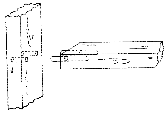
Fig. 264-8 Dowelled butt
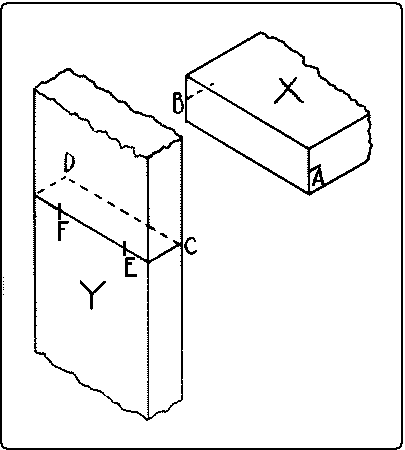
Fig. 246. Lay-out by Thru Dowling.
In a doweled butt-joint the dowels may go clear thru the outside member, and be finished as buttons on the outside, where they show. To lay out this joint mark near the ends of the edges of the abutting member, X, Fig. 246, center-lines A B. Draw on the other member Y, a sharp pencil-line to which when the lines AB on X are fitted, X will be in its proper place. Carry the line around to the other side of Y and locate on it the proper centers for the dowel-holes E and F. Then fasten on the end of X a handscrew in such a way that the jaws will be flush with the end. With another handscrew, clamp this handscrew to Y in such a way that the marks on the two pieces match, A to C and B to D, Fig. 247. Bore at the proper places, E and F, holes directly thru Y into X.
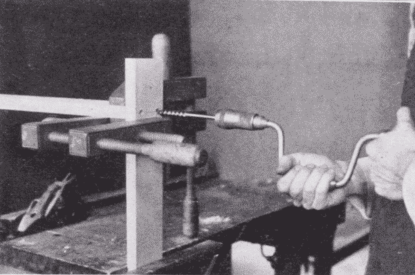
Fig. 247. Thru Boring for a Butt Joint.
Fig. 248 illustrates the gluing together of a four-legged stand in which the joints are made in this way. The cross-lap joints of the stretchers are first glued together, then the other joints are assembled without glue, to see that all the parts fit and finally two opposite sides are glued at a time. Pieces of paper are laid inside the gluing blocks to prevent them from sticking to the legs.
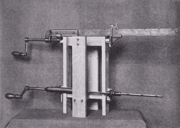
Fig. 248. Gluing-Up a Four-Legged Stand.
In case the dowels are to be hidden the chief difficulty is to locate the holes properly. One method of procedure is as follows: To dowel the end of one member against the face of the other as a stringer into a rail or a rail into a table leg, first lay out the position of the dowels in the end of the first member, X, Fig. 249. Gage a center-line, A B, across this end lengthwise, locate the centers of the dowel-holes, and square across with a knife point, as CD and EF. Gage a line on the other member to correspond with the line AB. On the face so gaged, lay the first member on its side so that one arris lies along this gaged line and prick off the points D and F, to get the centers of the dowel-holes.
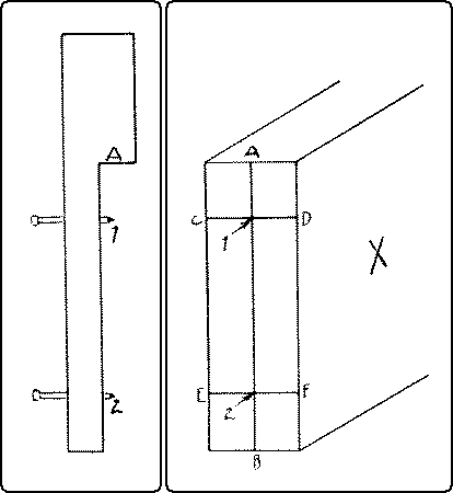
Fig. 249. Laying out a Dowel Joint.
If, as is usual, there are a number of similar joints to be made, a device like that shown in Fig. 249 will expedite matters. 1 and 2 are points of brads driven thru a piece of soft wood, which has been notched out, and are as far apart as the dowels. A-1 is the distance from the working edge of the rail to the first dowel. The same measure can be used from the end of the leg.
When the centers are all marked, bore the holes. Insert the dowels into the holes and make a trial assembly. If any rail is twisted from its proper plane, note carefully where the error is, take apart, glue a dowel into the hole, that is wrong, pare it off flush with the surface, and re-bore in such a place that the parts, when assembled will come up true. When everything fits, glue and clamp together.
No. 9. A toe-nailed joint is made by driving nails diagonally thru the corners of one member into the other. It is used in fastening the studding to the sill in balloon framing.
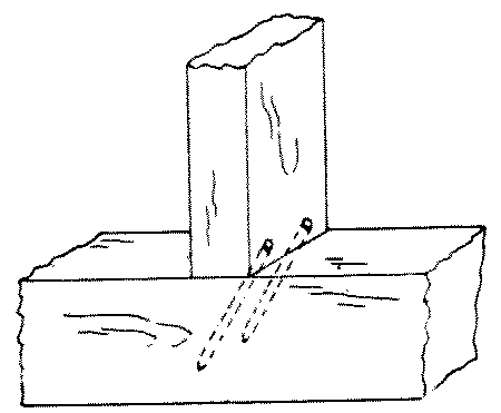
Fig. 264-9 Toe-nailed
No. 10. A draw-bolt joint is made by inserting an iron bolt thru a hole in one member and into the other to meet a nut inserted from the side of the second member. It is very strong and is used in bench construction, wooden machinery, etc.
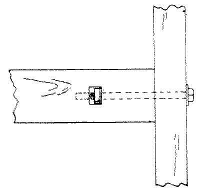
Fig. 264-10 Draw-bolt
No. 11. A plain butt-joint is one in which the members join endwise or edgewise without overlapping. It is used on returns as in ordinary boxes and cases.
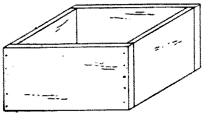
Fig. 264-11 Plain butt
No. 12. A glued and blocked joint is made by gluing and rubbing a block in the inside corner of two pieces which are butted and glued together. It is used in stair-work and cabinet-work, as in the corners of bureaus.
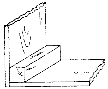
Fig. 264-12 Glued and blocked
No. 13. A hopper-joint is a butt-joint, but is peculiar in that the edges of the boards are not square with their faces on account of the pitch of the sides. It is used in hoppers, bins, chutes, etc. The difficulty in laying out this joint is to obtain the proper angle for the edges of the pieces. This may be done as follows: After the pieces are planed to the correct thickness, plane the upper and lower edges of the end pieces to the correct bevel as shown by the pitch of the sides. Lay out the pitch of the sides of the hopper on the outside of the end pieces. From the ends of these lines, on the upper and lower beveled edges score lines at right angles with the knife and try-square. Connect these lines on what will be the inside of the hopper. Saw off the surplus wood and plane to the lines thus scored. The side pieces may be finished in the same way, and the parts are then ready to be assembled.
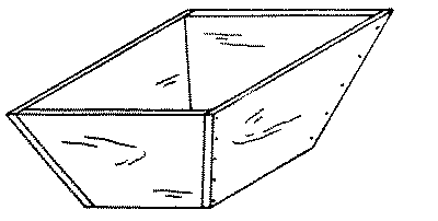
Fig. 264-13 Hopper
INDEX: Handwork in Wood