The plane is a modified chisel. The chief difference in action between a chisel and a plane in paring is this: the back of the chisel lies close down on the surface of the wood that is cut, and acts as a guide; whereas, in the plane, the cutter is elevated at an angle away from the surface of the wood, and only its cutting edge touches the wood, and it is held and guided mechanically by the plane mechanism. In other words, a plane is a chisel firmly held in a device which raises the cutter at an angle from the work, regulates the depth of the cut, and favors the cutting rather than the splitting action. An illustration of a chisel converted into a plane is the adjustable chisel-gage, Fig. 99.
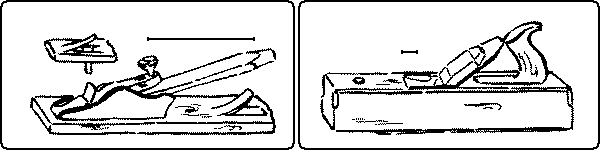
Fig. 99. Adjustable Chisel-Gage. Fig. 100. Wooden Bench-Plane.
The plane has developed as follows: it was first a chisel held in a block of wood. This is all that oriental planes are now, simply a sharpened wedge driven into a block of wood. When the hole works too loose, the Japanese carpenter inserts a piece of paper to tighten it, or he makes a new block. The first improvement was the addition of a wooden wedge to hold in place the “plane-iron”, as the cutter was formerly called. In this form, the cutter or plane-iron, tho still wedge-shaped, was reversed, being made heavier at the cutting edge in order to facilitate fastening it in the wooden plane-stock by means of the wooden wedge. Then a handle was added for convenience. Then came the cap, the object of which is to break back the shaving and thus weaken it as soon as possible after it is cut. Until a few years ago, this was all that there was in a plane, and such planes are still common, Fig. 100. Finally there appeared the iron plane, Fig. 101, with it various mechanical adjustments. The following are the parts of the Bailey iron plane:4
Footnote 4: The numbers and names in italics are those given in Stanley’s Catalog, No. 34. Some of these names, as “plane-iron,” are survivals from the days of the wooden plane and are obviously unsuitable now.
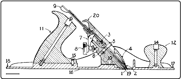
Fig. 101 Section of Jack Plane.
1. Cutter, or bit, or blade, or plane-iron.
2. Cap, or plane-iron cap, or curling iron.
3. Cutter screw, or plane-iron Screw.
4. Clamp, or lever cap, or wedge.
5. Clamp screw, or cap screw.
6. Frog.
7. Y Adjustment.
8. Brass set screw, or brass adjusting nut.
9. Lever (for lateral adjustment).
10. Frog screw.
11. Handle.
12. Knob.
13. Handle bolt and nut.
14. Knob screw, or Knob bolt and nut.
15. Handle screw.
16. Bottom, or sole.
17. Toe.
18. Heel.
19. Throat.
20. Thumb piece, or clamp lever, or cam.
There are various principles involved in the action of the plane. The effect of the flat sole is to regulate the cut of the cutter. If the surface be uneven, the cutter will not cut at all, or but little, in passing over low places, since the toe and heel of the sole will then be resting on higher places; but when the cutter reaches a high place a shaving will be taken off. Hence it follows that the longer the plane, the straighter will be the surface produced. The length of the plane used is determined by the length of the wood to be planed, and the degree of straightness desired.
The part of the sole directly in front of the cutter presses firmly down on the wood and so prevents the shaving from splitting far in advance of the edge. It follows that the narrowness of the mouth in a plane is an important factor in the production of smooth surfaces. This can be regulated by adjusting the toe in the block-plane, and by moving the frog in the jack- and smooth-planes.
A recent improvement in jack-, smooth-, and fore-planes consists of an adjustable frog, by means of which the throat can be narrowed or widened at will by means of a set-screw in the rear of the frog without removing the clamp and cutter. It is made by Sargent and Company. The Stanley “Bed Rock” plane has a similar but less convenient device.
The splitting of the wood in advance of the edge is also prevented by the breaking of the shaving as it hits against the cutter or its cap. Hence the advantage of bending up and breaking or partly breaking the shaving as soon as possible after it is cut. This shows why the cap is set close to the edge of the cutter. Another reason is that it thereby stiffens the cutter and prevents “chattering.” If a thick shaving be desired the cap has to be set farther back. In a smooth-plane 1⁄32 inch is enough, in a jack-plane ⅛ inch is often desirable. The following are the planes in common use:
The jack-plane, Fig. 102, 14″ to 15″ long, is the one used where a considerable amount of material is to be taken off to bring a piece of wood to size, and therefore the outline of the cutting edge instead of being straight is slightly curved or “crowned” so that in planing the surface of a board it makes a series of shallow grooves, the ridges of which must afterward be smoothed off by another plane. Also for beginners whose hands are not strong it is sometimes wise to grind the cutter with some “crown”, in order to take off narrow shavings, which require less strength. For school use, where the jack-plane is used for all purposes, the cutter is usually ground almost straight and only the corners rounded as in the smooth-plane and the fore-plane.5
Footnote 5: In whetting a plane-bit, a slight crown may be given it by rubbing a bit harder at the ends of the edge than in the middle. Strop in the same way as a chisel.
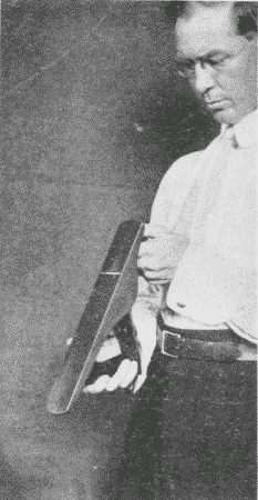
Fig. 102. Sighting Along the Sole of Jack-Plane.
The fore-plane, 22″ to 26″ long, and the jointer, 28″ to 30″ long, are large planes, similar to the jack-plane, except that the cutting edge is straight. They are used for straightening and smoothing long pieces.
The smooth-plane, 5½” to 10″ long, is a short plane, similar to the jack-plane, except that the cutting edge is straight. It is used for smoothing.
These four planes, the jack-plane, the fore-plane, the jointer, and the smooth-plane, are essentially alike, and directions for the use of one apply to all.
There are two chief adjustments in the Bailey iron plane: the brass set-screw, see 8 in Fig. 101, which regulates the depth of the cut, and the lever, 9, which moves the cutter sidewise so that it may be made to cut evenly. The skilful worker keeps constant watch of these adjustments. It is well to form the habit of always sighting along the sole before beginning to plane, in order to see that the cutter projects properly, Fig. 102. It is a common mistake among beginners to let the cutter project too far.
It is important to know what is the best order of procedure in planing up a board. There are often reasons for omitting the planing up of one or more surfaces, but it is wise to form the habit of following a regular order, and the following is suggested as a good one:
1. Working face. Plane one broad side flat and smooth. Finish with the plane set to cut line shavings. Test with try-square. Mark this face with a distinct pencil mark, A, Fig. 103.
2. Working edge. Plane one narrow side straight and square with the working face. Test with try-square, pressing the block of the try-square against the working face. Mark the working edge with two distinct pencil marks, B, Fig. 103.
3. End. First mark the width on the working face with the marking-gage, C, 1-2, Fig. 103. Chisel off the corner, a, of the piece outside this gaged line. True and smooth this end with the plane, making it square with both working face and working edge, D, 2, 3, 4, Fig. 103.
4. Length. Measure the length from the finished end, D, 2-3-4, score across the working face, D, 5-6, and working edge, D, 6-7, using a sharp knife point and the try-square. Saw just outside this line, D, 5-6-7, with the back-saw, cut off the narrow corner, D, b, beyond the gaged line and plane true, E, Fig. 103.
5. Width. Plane to the center of the gaged line, E, 1-2. Test this edge from the working face, F, Fig. 103.
6. Thickness. Mark the thickness with the marking-gage all around the piece, F, 8-9-10. Plane to the center of the gaged line, G, Fig. 103. Test this face for flatness.
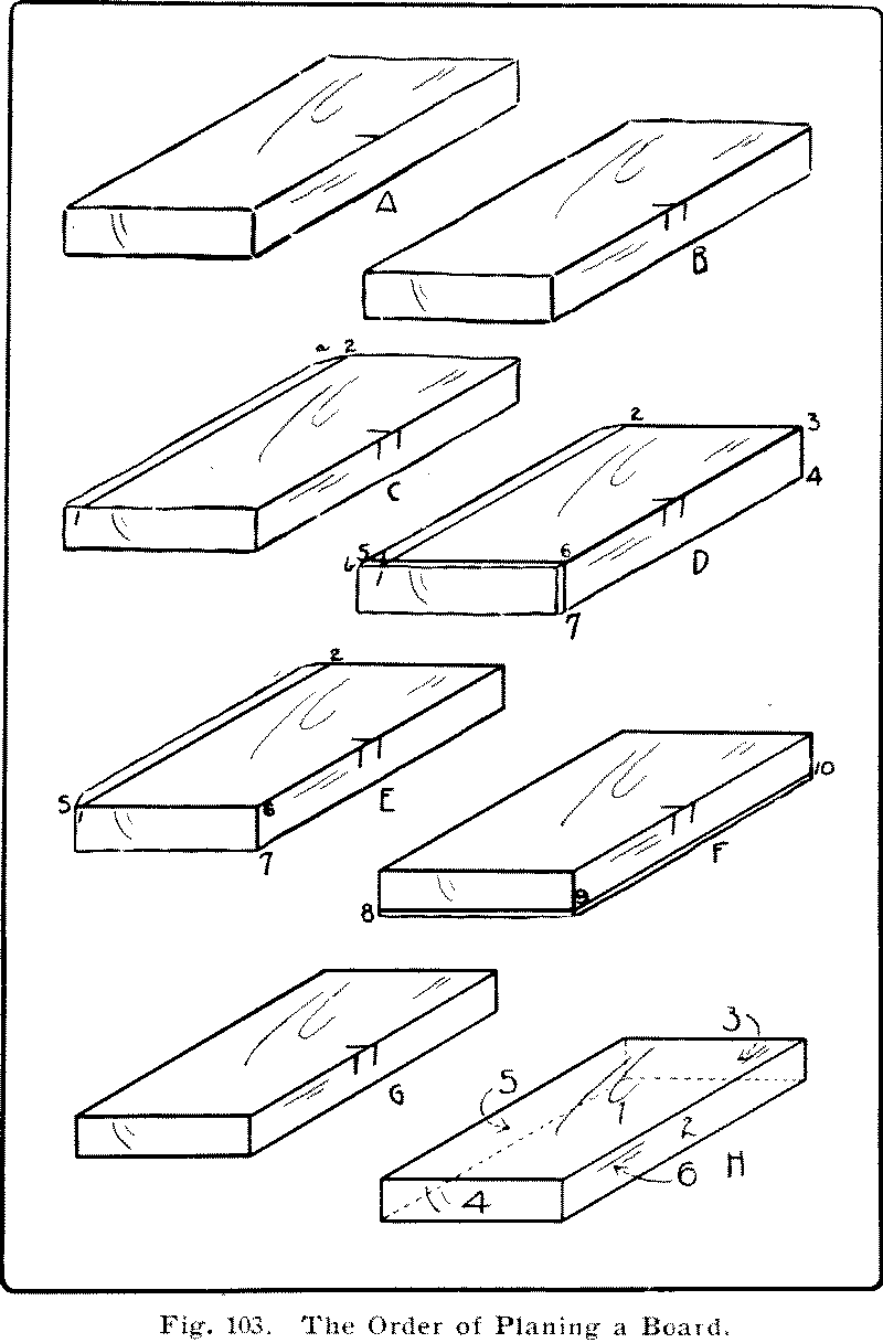
Fig. 103. The Order of Planing a Board.
In a word, the order to be followed is graphically represented in H, Fig. 103. The surfaces are numbered consecutively in the order in which they are to be planed.
The advantages of this order are these: by planing the working face first, a broad surface is secured to which the others may be made true. By planing the ends before the width is planed, the danger of splitting off fragments can be avoided by chiseling the corner of the unfinished edges, C, a, and D, b, Fig. 103, into a buttress. By planing the ends and the width before the thickness is planed, a dressed face is secured all around for gaging the thickness. In following this order all measurements and markings are made on a dressed face.
If there be any “wind” or twist in the board, this should be discovered first of all. This may be done roughly by sighting across the broad side of the board, Fig. 104, and more accurately by the use of “winding sticks,” see Fig. 205. Or the surface may be tested with the plane itself by tilting the plane on its long corner edge, and resting it on the board, while the worker looks between the board and the plane toward the light. It is evident that the plane must be turned in various directions to test for wind, and that a board only as long or as wide as the plane is long can be tested in this way. The try-square or any straight edge may be used for the same purpose, Fig. 105. If there be any wind in the board, this should at once be taken out of one face by planing down the high corners.
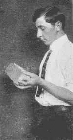
Fig. 104. Sighting for Wind. |
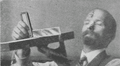
Fig. 105. Testing from Edge to Edge. |
In starting to plane, the worker should bear down on the knob at the front end of the plane. When the plane is well on the board, he should bear down equally on both knob and handle, and as the plane begins to pass off the board he should put all the pressure on the handle end, Fig. 106. By taking pains thus, a convex surface will be avoided, the making of which is a common error of beginners. On the return stroke, the plane should be lifted or tilted so that the cutting edge will not be dulled by rubbing on the wood. This is especially important on rough and dirty boards, as it saves the cutting edge, and in fine work, as it saves the work. If the plane tear the wood instead of cutting it smooth, as it should, it is because the planing is “against the grain”. This can often be avoided by noticing the direction of the grain before beginning to plane. But even if it be not noted beforehand, a stroke or two will show the roughness. In such a case, it is necessary simply to turn the wood around.
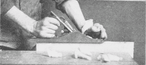
Fig. 106. Planing an Edge.
The accuracy of the work as it progresses should frequently be tested, and the eye should constantly be trained so that it can more and more be depended upon to detect inaccuracy, Fig. 107. As each surface is trued, it should be carefully smoothed with the cutter set to cut fine shavings.
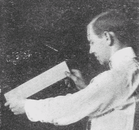
Fig. 107. Sighting an Edge.
In planing a very cross-grained piece of wood, there are several methods to use for securing a smooth surface. The frog of the plane should be moved forward so that the throat in the front of the cutter is a mere slit. In the ordinary plane it is necessary to remove the cutter in order to reset the frog, but in the Sargent plane and the Stanley “bed rock” plane, it can be set by a set-screw at the rear of the frog. Next, the cap should be set so that the cutter projects but very little beyond it, or, in technical language, the cutter should be set “fine.” A sliding cut, see, should be taken with the plane, and sometimes it may be necessary to move the plane nearly at right angles to the general direction of the grain. By these means even refractory pieces of wood can be well smoothed. See also scrapers.
The choking of a plane is the stoppage of the throat by shavings. It may be due simply to the fact that the cutter is dull or that it projects too far below the sole of the plane. In a wooden plane choking is sometimes due to the crowding of shavings under some part of the wedge. When the adjustable frog in a modern plane is improperly placed choking may result. The frog should be far enough forward so that the cutter rests squarely upon it.
Choking may, and most commonly does, take place because the cap does not fit down tight on the cutter. This happens if the cap be nicked or uneven. In consequence, minute shavings are driven between these two irons and choking soon results. The remedy is to sharpen the cap, so that its edge makes a close fit with the cutter. The fit may be made still tighter by rubbing with a screwdriver the edge of the cap down on the cutter after it is screwed in place.
In no tool is it more important to keep the cutter sharp than in the plane. To remove the cutter, in order to sharpen it, first loosen the clamp lever and remove the clamp. Carefully remove the cap and cutter taking pains not to let the edge hit any part of the plane, then using the clamp as a screwdriver, loosen the cap-screw and slide the cap back along the slot in the cutter, where it can be held fast by a turn of the cap-screw. The edge is now free and can readily be whetted. When the cap needs to be entirely removed, for instance, for grinding, after it has been slid along the cutter slot, as before, it is turned at right angles to the cutter, and then slid down the slot until the cap-screw unbuttons from the cutter. The object in sliding the cap up the slot before turning it, is to prevent the danger of injuring the edge. Some caps are now made with the buttonhole at the upper end of the slot.
After sharpening, the order is reversed for replacing the cutter. The cap is set at right angles to the cutter, the cap-screw dropped into the slot, the cap is slid up the slot, and turned into line with the cutter, and then slid down the slot till the edge of the cap comes quite near the edge of the cutter. Then the two are held firmly together with the left hand until the cap screw is turned tight.
In replacing the cutter and cap in the plane, care should be taken not to injure the edge and to see that the Y adjustment lever fits into the little slot in the cap; then finally the lever is thrown down tight. Then, by turning the plane sole upward and glancing down it, the proper adjustments with the brass set-screw and lateral adjustment lever are made. When the plane is not being used, it should rest either on a pillow (a little strip of wood in the bench trough), or on its side. In no case should it be dropped sole down flat on the bench.
The block-plane, Fig. 108, gets its name from the fact that it was first made for planing off the ends of clap-boards, a process called “blocking in”.
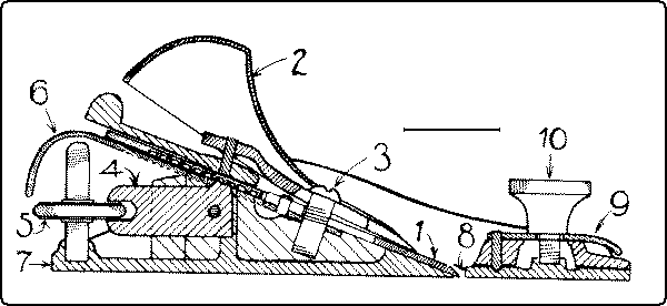
Fig. 108. Section of Block-Plane.
The names of the parts of the Bailey block-plane are6:
1. Cutter or bit or plane-iron.
2. Clamp or lever cup.
3. Cap-screw.
4. Adjusting lever.
5. Adjusting nut.
6. Lateral adjustment.
7. Bottom.
8. Mouth piece.
9. Eccentric plate.
10. Knob.
The block-plane was devised for use with one hand, as when it is used by carpenters in planing pieces not readily taken to a vise or in planing with a bench-hook. Hence it is made small, 3½” to 8″ long, the clamp is rounded so as to act as a handle, and the cutter is lowered to an angle of about 20° to make the plane easy to grasp. The lower angle of the cutter makes it necessary that the bevel be on the upper side. Otherwise, to give clearance, the bevel would have to be made so long and so thin as to be weak. By putting the bevel up, the angle between the wood and the cutter is maintained practically as in the smooth-plane. Since the block-plane is intended chiefly for use on end grain, no cap is needed to break the shavings. The adjustable throat makes it possible to cut a very fine shaving. To facilitate the cutting action, several forms of block-planes with a very low angle are now made.
Where both hands are free to hold the plane, the block-plane has no advantage over a smooth-plane, even on end grain. Moreover, the cutter cannot be held so firmly in place as that of a smooth-plane, so that it requires constant adjustment. Hence it is not an easy tool for amateurs to handle. There is considerable lost motion in the adjusting nut, and the set-screw, which acts as a knob, is likely to work loose and be lost. It is hardly to be recommended as a part of the equipment of the individual bench in school shops.
The piece to be planed with the block-plane may be held either in the vise, end up, or on a bench-hook, Fig. 109. In end planing in the vise, in order to avoid splintering the precaution should be taken to trim off a corner on the undressed edge, as directed on page, or else the planing must be done from both edges toward the center. The sliding cut is much easier than the straight cut, and hence there is a constant temptation to turn the plane at an angle perhaps at an expense of the flat surface desired.
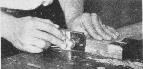
Fig. 109, Using the Block-Plane and Bench-Hook.
In using the bench-hook the piece to be block-planed is placed with the working edge against the block, with the end to be planed to the right and flush with the edge of the bench-hook, in which position it is held with the left hand. The block-plane, held in the right hand, is placed on its side on the bench facing toward the work. In planing, the left hand holds the work firmly against the block of the bench-hook, pressing it somewhat to the right against the plane. The right hand holds the side of the plane flat on the bench and presses it to the left against the bench-hook and work. Held in this position the plane is pushed forward and back until the end is smoothed. Considerable practice is necessary to handle the block-plane well.
The scrub-plane is a short plane in which the crown of the cutter, Fig. 110, is quite curved. It is used to reduce surfaces rapidly.
The scratch-plane, Fig. 111, has a toothed cutter which scratches fine lines along its course. It is used to roughen surfaces of hard wood which are to be glued together, for otherwise the glue would not adhere well. Some tropical woods are so hard that their surfaces can be reduced only by a scratch-plane. It is also useful in preparing the surface of a very cross-grained piece of wood which cannot be planed without chipping. By first scratching it carefully in all directions, it can then be scraped smooth. It is also called a scraper-plane, because accompanying the plane is a scraper which can be inserted in the same stock and inclined at any required angle. This plane-stock prevents the scraper from unduly lowering some portions of the surface. See also veneer-scraper.
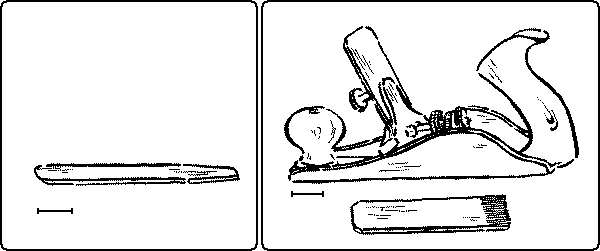
Fig. 110. Cutter of Scrub-Plane. Fig. 111. Scratch-Plane and Scraper-Plane.
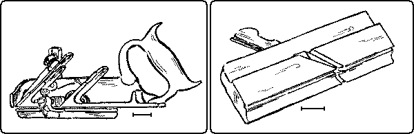
Fig. 112. Rabbet-Plane. Fig. 113. Molding-Plane.
The rabbeting- or rebating-plane, Fig. 112, is designed for use in cutting out a rectangular recess, such as the rabbet on the back of the picture-frames. In line with the right hand corner of the cutter is a removable spur to score the wood so that the shaving which follows may be cut out clean and not torn out. With the addition of a guiding fence it is called a filletster. This may be used on either the right or left side. In the form shown in Fig. 112, there is also a depth gage.
In using this plane see that the corner of the cutter is in line with the sole, and that both it and the spur are sharp. Set the fence and the stop at the desired width and depth of the rabbet. At the first stroke the spur will score the width. This and every stroke should be taken as evenly and carefully as if it were the only one. In the effort to keep the fence pressed close to the side of the wood, the tendency is to tilt the plane over. This causes the very opposite effect from that desired, for the spur runs off diagonally, as in Fig. 114.
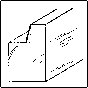
Fig. 114. Result of Careless use of Rabbet-Plane.
If this happens stop planing at once, clean out the recess properly with a chisel and then proceed.
The dado-plane is much like the rabbeting-plane, except that it is provided with two spurs, one at each side of the cutting edge, to score the wood before cutting.
The molding-plane, Fig. 113, as it name indicates, is for making moldings of various forms; as, quarter-round, half-round, ogee, etc.
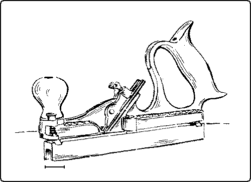
Fig. 115. Tonguing-and-Grooving Plane.
The tonguing-and-grooving-plane, Fig. 115, is for matching boards, i. e. making a tongue in one to fit into a groove in another. See Fig. 269.
The circular-plane, Fig. 116. has a flexible steel face which can be adjusted to any required arc, convex or concave, so that curved surfaces may be planed.
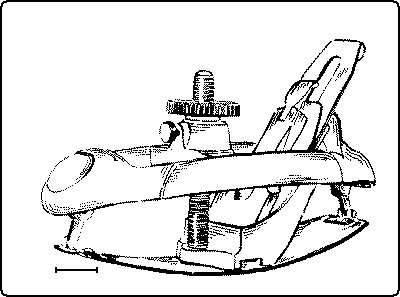
Fig. 116. Circular-Plane.
The universal plane, Fig. 117, is a combination of various molding-, rabbeting-, matching- and other planes. It is capable of many adjustments and applications. The principal parts of this plane are: a main stock, A, with two sets of transverse sliding arms, a depth-gage, F, adjusted by a screw, and a slitting cutter with stop, a sliding section, B, with a vertically adjustable bottom, the auxiliary center bottom, C, to be placed when needed in front of the cutter as an extra support or stop. This bottom is adjustable both vertically and laterally. Fences, D and E. For fine work, fence D has a lateral adjustment by means of a thumb-screw. The fences can be used on either side of the plane, and the rosewood guides can be tilted to any desired angle up to 45°, by loosening the screws on the face. Fence E can be reversed for center-beading wide boards. For work thinner than the depth of the fence, the work may overhang the edge of the bench and fence E be removed. An adjustable stop, to be used in beading the edges of matched boards, is inserted on the left side of the sliding section B. A great variety of cutters are supplied, such as: molding, matching, sash, beading, reeding, fluting, hollow, round, plow, rabbet, and filletster. Special shapes can be obtained by order.
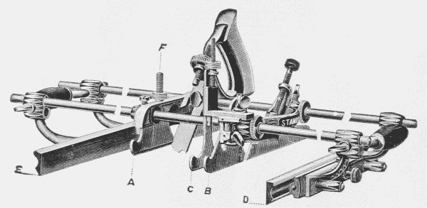
Fig. 117. Universal Plane.
The Use of the Universal Plane. Insert the proper cutter, adjusting it so that the portion of it in line with the main stock, A, will project below the sole the proper distance for cutting.
Adjust the bottom of the sliding section, B, so that the lowest portion of the cutter will project the proper distance below it for cutting. Tighten the check nuts on the transverse arms and then tighten the thumb-screws which secure the sliding section to the arms. The sliding section is not always necessary, as in a narrow rabbet or bead.
When an additional support is needed for the cutter, the auxiliary center bottom, C, may be adjusted in front of it. This may also be used as a stop.
Adjust one or both of the fences, D and E, and fasten with the thumb-screws. Adjust the depth-gage, F, at the proper depth.
For a dado remove the fences and set the spurs parallel with the edges of the cutter. Insert the long adjustable stop on the left hand of the sliding section. For slitting, insert the cutter and stop on the right side of the main stock and use either fence for a guide.
For a chamfer, insert the desired cutter, and tilt the rosewood guides on the fences to the required angle. For chamfer beading use in the same manner, and gradually feed the cutter down by means of the adjusting thumb-nut.
There are also a number of planelike tools such as the following:
The spoke-shave, Fig. 118. works on the same principle as a plane, except that the guiding surface is very short. This adapts it to work with curved outlines. It is a sort of regulated draw-shave. It is sometimes made of iron with an adjustable mouth, which is a convenient form for beginners to use, and is easy to sharpen. The pattern-makers spokeshave, Fig. 119, which has a wooden frame, is better suited to more careful work. The method of using the spokeshave is shown in Fig. 120.
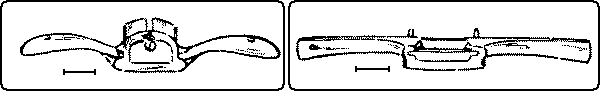
Fig. 118. Iron Spokeshave. Fig. 119. Pattern-maker’s Spokeshave.
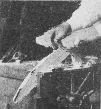
Fig. 120. Using a Spokeshave.
The router-plane, Figs. 121 and 122, is used to lower a certain part of a surface and yet keep it parallel with the surrounding part, and it is particularly useful in cutting panels, dadoes, and grooves. The cutter has to be adjusted for each successive cut. Where there are a number of dadoes to be cut of the same depth, it is wise not to finish them one at a time, but to carry on the cutting of all together, lowering the cutter after each round. In this way all the dadoes will be finished at exactly the same depth.

Fig. 121. Router-Plane.
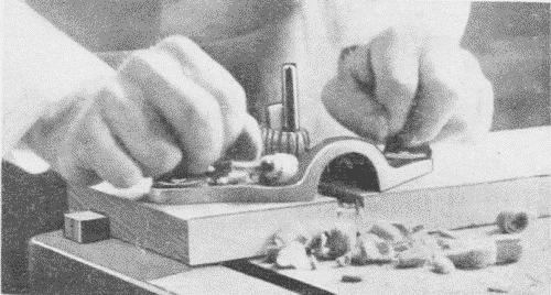
Fig. 122. Using a Router-Plane.
The dowel-pointer, Fig. 123, is a convenient tool for removing the sharp edges from the ends of dowel pins. It is held in a brace. The cutter is adjustable and is removable for sharpening.
The cornering tool, Fig. 124, is a simple device for rounding sharp corners. A cutter at each end cuts both ways so that it can be used with the grain without changing the position of the work. The depth of the cut is fixed.
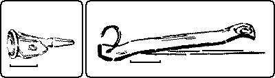
Fig. 123. Dowel-Pointer. Fig. 124. Cornering Tool.
INDEX: Handwork in Wood