A bridle joint is often defined as the reverse of a mortise and tenon, and is chiefly used in the carpentry and joinery trades. The name probably originated from the fact that it bears some resemblance to the manner in which a bit slips into the horse’s mouth and is fastened to the bridle. There are fewer varieties of the bridle joint than of the halved or the mortise and tenon; and this being the case we may take the opportunity of giving a few detailed directions, with explanatory illustrations, on the setting out and the making.
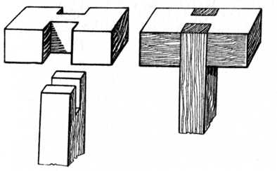
Fig. 72 shows a bridle joint in what is perhaps its simplest form, the separate pieces being given at the left and the completed joint at the right. A joint of this type may be applied in nearly all cases where a halved or a mortise and tenon joint could be used. Bridle joints have an advantage as regards appearance over the mortise and tenoned variety in cases such as Fig. 73, which shows an occasional table leg fitted to the circular top framing. The bridle joint here allows the grain of the leg to run through to the top, and gives a better and more workmanlike appearance to the completed article.
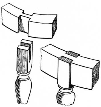
Fig. 74 is a “Mitred bridle joint,” the part a showing the upright portion separated. This is a most useful joint for positions similar to that shown in the small glass frame, Fig. 75. The wood framing in this case is only 13⁄8 in. in width, and if a mortise were used it would have to be exceptionally small. The shaped rail at the bottom of this frame again shows the application of the bridle joint.
Fig. 76 shows an “Oblique bridle joint,” used in many instances as a brace, or strut, to prevent framing from racking. (See also Figs. 31 and 32.)
Fig. 77 is a “Stopped bridle joint,” used in positions where the top or bottom edge of the work meets the eye, and where, if the rail were allowed to run through, the end grain would appear unsightly.
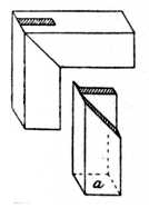
Fig. 74.—Mitre Bridle Joint. |
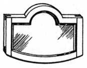
Fig. 75.—Mirror Frame with Bridle Joints. |
Fig. 78 is a so-called bridle-joint at the corner of a frame. This is also called an “Open slot mortise and tenon joint,” a good strong, serviceable joint which can be used instead of the closed mortise and tenon type, its advantage being that less labour is required in the making. (See also Fig. 169.)
Fig. 79 is an “Oblique angle bridle joint,” used in similar positions to the above, but when the two pieces meet at an acute angle at the end of a frame.
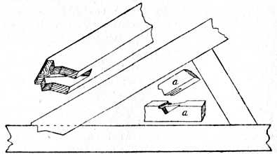
Fig. 80 shows the application of the bridle joint to a roof truss. Two sketches are shown at the joining of the tie beam and the principal rafter. The joint a is the type generally used. (See also Fig. 71 for the joints in a queen post roof.)
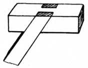
Fig. 76.—Oblique Bridle Joint. |
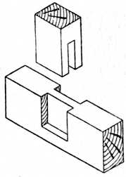
Fig. 77.—Stopped Bridle Joint. |
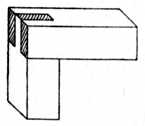
Fig. 78.—Bridle Joint at Corner of Frame. |
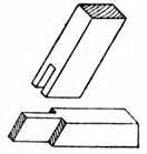
Fig. 79.—Oblique Angle Bridle Joint. |
Setting Out and Marking.—It is a safe rule, when setting out a bridle joint, to divide the thickness of the timber into three equal parts. This will leave the timber on each side of the tongue equal to the thickness of the tongue, thus giving uniform strength to the joint. The bridle joint is chiefly used for connecting the internal parts of wooden frames. It is stronger than the halving joint, and, owing to its peculiar construction, requires little in the way of pegs, screws or nails to secure it in position. Fig. 81 illustrates the joint, both open and closed.
To understand the method of setting out and marking, glance at the sketch, Fig. 81. It is not necessary that the bridle piece A be the same width as the cross piece B; but it must be remembered when setting out the joint with the marking knife or pencil that the width marked W on piece B must be equal to the width W on the piece A. The timber should be fairly accurately sawn or planed to the same thickness, and all edges should be square and true.
The wood is placed upon the bench, and the joint marked out by using a marking knife or penknife blade and the try square. A knife blade is much better than a pencil, as the sharp edge severs the fibres of the wood and gives a finer line than the pencil. It is not always necessary to exactly square and trim the end of piece A; it may with advantage in many cases be left at least 1⁄4 in. longer than necessary and levelled off with the saw, plane and chisel after the joint is put together. (See Method of Cutting in Fig. 92, page 47.)
When the piece A has to have a bridle joint fitted at each end, it is customary to cut the timber about 3⁄8 in. longer than necessary, and mark the shoulder lines C to the exact length, after which the joints are cut. This leaves the ends standing over the horizontal rails, and, after fixing the complete frame together, the small projecting ends are levelled off flush with the cross rails.
Gauging.—After squaring all the shoulder lines round the timber with the knife and try square, the mortise gauge should be set so as to strike the two gauge lines marked G, Figs. 83 and 84, at one operation. If the worker does not possess a mortise gauge the lines may be marked at two distinct operations with the aid of the marking gauge (Fig. 82). The gauge should be adjusted so as to mark the wood into thirds, and the stock of the gauge (the portion of the gauge containing the thumb screw in Fig. 82) must be used from the face side of the timber when gauging up the whole of the pieces forming a frame. The face mark on the work is indicated by a glorified comma, and the edge mark is shown by X, as in the various illustrations. Fig. 82 shows the method of holding the gauge in the right hand whilst gauging the lines on the work.
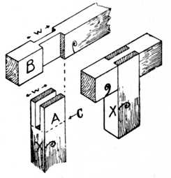
Fig. 81.—Bridle Joint, open and closed. |
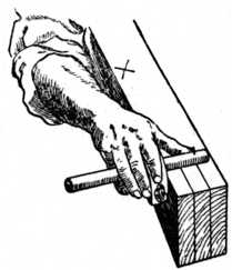
Fig. 82.—Gauging the Timber. |
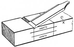
The joint, when marked out, will appear as at Figs. 83 and 84, and the portions which are to be cut away may be shaded with a pencil as indicated; this will prevent mistakes arising whilst cutting the work, especially by one who is not thoroughly familiar with the joint.
The distance A B, in Fig. 84, must not be less than the distance A B in Fig. 83.
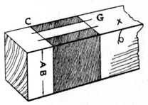
Fig. 83. |
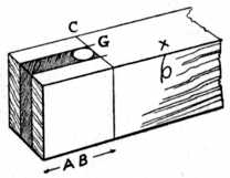
Fig. 84. |
The Two Parts of the Joint Marked.
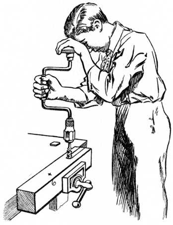
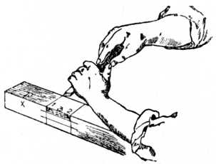
Boring Away Waste.—Examine Fig. 84; the shaded portion in the centre has to be cut away, and it will greatly facilitate the removal of this waste piece by boring a hole with a twist bit at the position shown. The twist bit should be about 1⁄8 in. less in diameter than the width between the gauge lines G. The easiest method of boring out this hole is shown at Fig. 85, which gives the correct position of the worker.
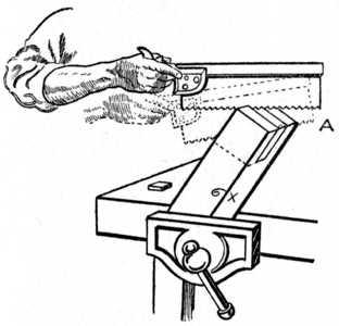
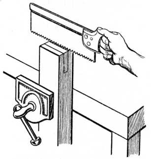
Sawing.—The wood should be put in the vice as Fig. 86. Taking up a saw, with the index finger on the side of the handle, commence sawing, and proceed until you come to the position indicated by the dotted hand and saw A; this will leave a saw kerf or cut running diagonally from the shoulder line to corner of the wood. Release the vice and refix the wood so that it leans in exactly the opposite direction to Fig. 86; then reverse your own position and repeat the sawing, so as to cut another diagonal saw cut from the shoulder line to the corner. Fix the wood upright, as shown at Fig. 87, and saw as shown, when you will find that the saw has no tendency to run out of the guide cuts already formed by the method used at Fig. 86. Remember, when commencing to saw at Fig. 86, that it is necessary to saw inside the gauge line; otherwise the joint will be too slack, owing to the amount of sawdust removed by the thickness of the saw blade. The index finger on the side of the saw, pointing in the direction of the saw cut, will greatly help the worker to saw in a straight line, as it is natural to point with this finger to any object that is to be aimed at.
Cut down the other line in a similar manner, and then with a chisel of suitable width carefully chop away the waste material. The wood may be placed edge way upon the bench, or in the vice, and the chisel should be held vertically. The hole which has been bored with the twist bit will allow the chips which are cut away to offer little or no resistance to the chisel blade. The chiselling should not all be done from one side, or a chipped under-edge will be the result; it is better to chisel the work until half-way through and then turn the other edge of the wood uppermost and again begin to chisel from the top. This method will finish the cutting in the centre of the work and prevent burred and ragged or chipped edges at the shoulder.
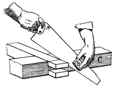
Cutting the Shoulders.—With regard to working the piece B, Fig. 81, place the wood against the bench stop or in the vice, and taking up a 3⁄4-in. chisel carefully cut away a small channel, as shown at Fig. 88; treat the other shoulder lines in a similar manner. If the marking knife or penknife blade has been used with a fair amount of pressure so as to score the fibres of the wood, this small channel, which is to form a guide for the saw, will quickly and easily be cut. Next place the wood in the vice or on the cutting board as shown at Fig. 89, and begin by sawing lightly at the back edge as shown. When the saw has entered the wood 1⁄4 in. gradually bring the handle down from position A to position B (dotted lines) whilst the saw is in motion. Continue sawing until just on the gauge line; then treat the other shoulder lines in a similar manner.

Chiselling away Waste.—Fix your wood firmly in any suitable manner, vice or otherwise, and, holding your chisel tilted as at Fig. 90, pare away the blacked portion 1; then pare away the blacked portion 2; after which hold the chisel flat and by gradual operations pare away the dotted lines 3, until you come down to the gauge line; then repeat the method of cutting on the opposite side of the wood. If any difficulty be experienced by chipped or ragged edges whilst chiselling, it can easily be overcome by chiselling alternately from the outside of the wood, so that the finish of the chisel cut takes place in the centre of the work. Some prefer to chisel away the waste by placing the wood on its edge and using the chisel vertically instead of horizontally. The same methods (1, 2 and 3) hold good in this case.
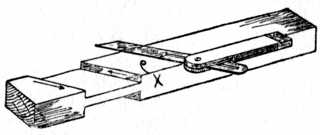
Joints Other than at 90°.—The two pieces forming a bridle joint are not always at right angles, as at Fig. 81; in many instances it is necessary that the joint be at other than 90 degrees. The work, however, is treated in a similar manner, with the exception that an adjustable joiner’s bevel is used instead of a try square to mark out the shoulder lines, and that a change of direction in the grain of the wood will occur when chiselling out the work. Fig. 91 indicates the change in the grain of the wood, and the adjustable joiner’s bevel is also shown.
<< BACK | INDEX: Woodwork Joints by William Fairham | NEXT >>