Dowelling is the term generally given to the method of jointing timber and other materials by wooden or metal pegs, which are called dowels. For cabinet-making and similar work straight-grained beechwood dowels are mostly used; these may be bought by the gross, in lengths of about 36 ins., and of any desired diameter.
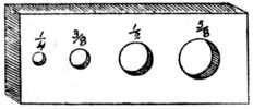
Making Dowels.—Many, however, prefer to make what they require for the work in hand, and the following is the method that is generally employed. Pieces of straight-grained wood are wrought to a square section, after which the corners are planed away to form an octagonal section. The sharp corners are now planed away, and the roughly formed dowel is driven through a steel dowel plate, Fig. 190, by the aid of a heavy hammer, thus giving the necessary roundness and finish to the dowels. When hammering dowels through a plate the hammer should on no account be allowed to come in contact with the face of the dowel plate, or the cutting edge of the hole will be spoilt. Simply drive the dowel to within 1⁄8 in. of the plate and knock it out with the next dowel.
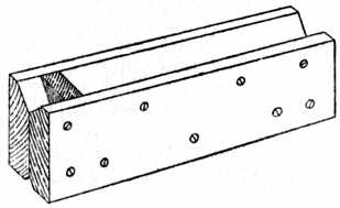
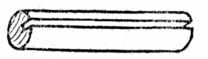
Fig. 192.—Dowel with Groove. |
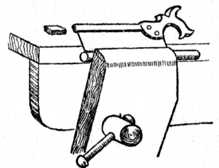
Fig. 193.—Sawing Groove in Dowel. |
To plane off the corners a “cradle” (Fig. 191) is made and kept for the purpose. The advantage of this cradle is obvious, preventing as it does any tendency of the partly-formed dowel to slip or wobble. A jig, or cradle, is easily made by bevelling the edges of two separate pieces of wood and then glueing and screwing them together as at Fig. 191. A small block of wood is inserted to act as a stop whilst the planing operation is in progress. It is usual to bevel both edges of the timber from which the cradle is formed, thus accommodating all sizes of dowels from 1⁄4 in. to 5⁄8 in. in diameter.
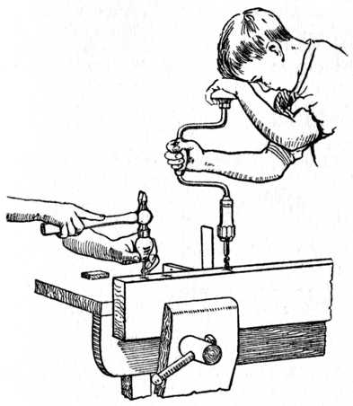 Fig. 194.—Pricking the Centres ready for Boring. Also showing how Brace is used in conjunction with Try Square.
Fig. 192 shows a completed dowel with a small groove running along its entire length. The object of this groove is to allow the air and superfluous glue to escape and thus avoid splitting the work on hand; the groove also secretes a certain amount of glue, which increases its hold on the timber.
Fig. 198 illustrates the method of marking out and gauging two boards for dowelling. The edges of the boards are first shot to a true joint; then the face sides are placed together and the lines for the dowels are marked across the edges with a fine pencil and the aid of a try square. The boards are then gauged from the face side, thus giving the points indicated in the sketch.
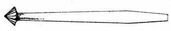
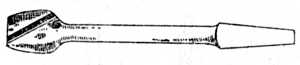 Fig. 196.—Dowel Rounder.
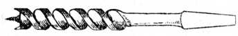
To start the twist bit (Fig. 197) it is a good plan to prick the board at the point of intersection of the marked lines with a sharp, circular-pointed marking awl. This obviates any tendency of the boring bit to run out of truth and thus cause unevenness on the face side of the jointed board. (See Fig. 194.)
A safe rule for the spacing of dowels when jointing sideboard tops, dressing table and wardrobe ends, etc., is to place the dowels 9 ins. to 10 ins. apart, and place two dowels at each end as shown at Fig. 198. The length of the dowels should be about 7⁄8 in. to 11⁄4 in. long.
Fig. 199 shows the two boards prepared ready for glueing. The back one is bored to receive the dowels, and the front one shows the dowels glued in position. It is customary to warm the edges of the boards before spreading the glue, and cramps are required to squeeze the joint tight. These should be left on the jointed board from one to four hours according to the state of the weather. In cases where thick timber (say 2-in. or 21⁄2-in. boards) is to be jointed, two rows of dowels may be used, the position of the dowels being as Fig. 200.
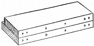
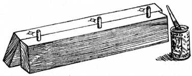
Fig. 201 shows the plan of a 3-in. cornice pole made to fit a bay window; the straight portions of the pole are generally turned in the lathe, the corner portions being afterwards jointed and worked up to the required shape. To avoid any difficulty in the setting out of the dowels, a disc of cardboard or sheet metal is made to the same diameter as that of the cornice pole; this disc is called a template. The positions of the dowels are set out geometrically, and the centres are pricked through with a fine-pointed marking awl (see sketch of template, a, Fig. 201). The template is put on the ends of the straight pole, and the dowel centres are pricked into the wood. The process is repeated on the ends of the corner block (b, Fig. 201), and if the holes be now bored at the centres indicated a true fit will be obtained.
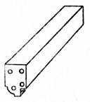
Fig. 200.—Method of Dowelling Thick Timber. |
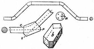
Fig. 201.—Method of Dowelling Cornice Pole by Means of Template. |
Fig. 201 c shows two portions of the circular pole jointed up to a corner block, and the dotted lines P indicate the direct line of pressure and shows the position for the cramp. When the glue is thoroughly set the corner block is sawn and spokeshaved to the desired shape as shown by the dotted line. This method is illustrated to show that, by the use of a suitable template, dowels may be exactly set out even when there is no straight or square face from which to use a marking gauge, and the method may, of course, be applied to many other examples of dowelling at the discretion of the workman.
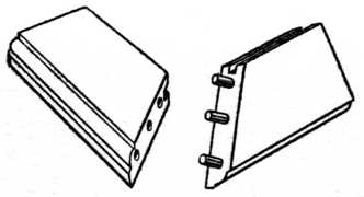
Fig. 202.—Dowelling a Mitred Frame. |
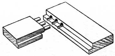
Fig. 203.—Method of Frame Dowelling. (Long and Short Shoulders.) |
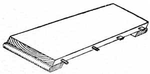
Fig. 204.—Table Leaf with Dowels. |

Fig. 205.— Block for Twist Bit. |
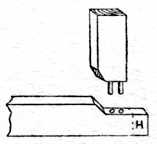
Fig. 206.—Dowelling for Moulded Frame. |
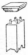
Fig. 207.— Cap. |
Fig. 202 shows one corner of a mitred and dowelled frame. It needs little or no explanation beyond the fact that the dowels should be at right angles to the line of joint, and consequently the dowel at the outside edge of the frame will have to be much shorter than the others. This gives a strong and serviceable joint, suitable for many purposes.
Frame Dowelling.—Fig. 203 shows one corner of a frame with long and short shoulders, such as occurs when the upright is rebated through its entire length. The holes in both pieces are bored for the dowels before they are rebated. This avoids any difficulty in endeavouring to bore with only one side of the twist bit in the wood. A similar type of joint is used on nearly all kinds of glass and door frames in cabinet work.
Fig. 204 is a leaf for the screw type of table. Circular dowels are shown at one end, and rectangular wooden pegs at the other; both methods are equally good, and, of course, the dowels are only glued into one leaf. The object of these dowels is to guide the table leaf into its proper position when the leaf engages the table proper, and to make the flat surface of the table top and leaf register correctly and thus ensure a level surface.
Fig. 205 is a wooden block made in two portions and held together by screws; it is used to fasten around a twist bit, the object being to ensure that all the dowel holes are of uniform depth. It may be adjusted as desired and firmly screwed round the twist bit; if the hole is made 1⁄4 in. in diameter it will clip round a 1⁄4-in. or 3⁄8-in. bit and will answer a dual purpose. It is a preventative for bad dowelling.
Fig. 206 is an example of dowelling framing when the moulding on the edge has to be mitred. It is necessary to cut the shoulders away so as to allow the members of the moulding to intersect. The section of the mould is not shown in the sketch for clearness of representation. The portion marked H is called the “horn,” and it is not cut off until after the frame is glued up; its object is to prevent the rail splitting or bursting when knocking up the frame or during the cramping process.
Fig. 207 shows the method of dowelling a moulded cap to the top of a wooden bedstead post or similar pillar where it is desired to avoid any unsightliness.
Fig. 208 is a dining-table leg and portion of the framing, showing the method of dowelling the frame to the leg. Chairs, couch frames, etc., are made in a similar manner.
Fig. 209 shows the top portion of a table leg and a home-made dowel gauge. The gauge is made of any hardwood, and steel wire pins are driven through at the required positions and sharpened similar to the spur of a marking gauge. The legs are sawn and planed up true and square, and the advantage of the gauge is that all legs are marked exactly alike and are therefore interchangeable until glued up. A gauge of this type is easily and quickly made and may be kept for its specific purpose or altered for other work.
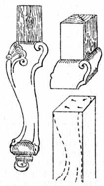
Fig. 210 indicates the Queen Anne type of leg, a sketch of same broken below the knee also being given. Here we have another type of irregular setting out, which is accomplished in the following manner. Saw and plane the broken portion of the leg true as shown; take the timber which is to be jointed and treat it in a similar manner; now place four ordinary pins on the lower portion. Carefully place the top portion to the required position and smartly give it one tap with the hammer; this will cause the pin-heads to leave indentations, and if these be taken as centres for boring, accurate work will result. The new portion of the leg is afterwards sawn and wrought to the desired shape.
This is an example of work where it is next to impossible to use a gauge, and as only one joint is required it is not worth the time taken to make a template.
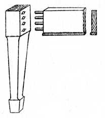
Fig. 208.—Dowelling a Dining-Table Leg. |
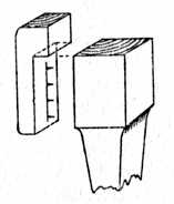
Fig. 209.—Dowel Gauge for Legs. |
The tools used in dowelling are: Brace, countersink, dowel-rounder, twist bit, try-square, marking-awl, and the usual bench tools. The first four are illustrated at Figs. 194, 195, 196 and 197 respectively.
The method of working is: Plane up, mark out, bore holes, countersink, glue dowels and complete joints.
<< BACK | INDEX: Woodwork Joints by William Fairham | NEXT >>