Although mitreing is used in everyday woodwork, it comes last in our list of regular joints simply because it has been partly dealt with in almost every previous chapter. For example, we have mitre halving in Fig. 34, a mitre bridle joint in Fig. 74, a tongued and grooved mitre in Fig. 116, mitred mortise and tenon joints in Figs. 148 and 159, a dowelled mitre frame in Fig. 202, and a mitred dovetail in Fig. 286.
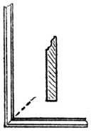
Fig. 321.— Mitred Skirting. |
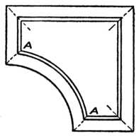
Fig. 322.— Curved Mitre. |
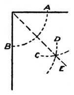
Fig. 323.— Halving the Angle. |
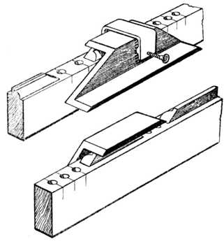
Mitreing.—The term mitreing is generally used to denote the type of joint used at the corner of a picture frame; or where two pieces of wood are bevelled away so as to fit each other, as the skirting or plinth mould at Fig. 321. In these cases the timber is cut so that the joint is at 45 degrees to the face, and the two pieces, when placed together, form an angle of 90 degrees (a right angle).
The term mitreing, however, is not confined to the fitting of timber around a right angle; it may be justly applied to the fitting of a moulding around an angle irrespective of the number of its degrees.
One often hears such terms as “a half mitre,” used to denote the fitting of a moulding around an octagonal column or pedestal, and probably it would be more correct to describe the joint as a mitre cut at 221⁄2 degrees. Mitreing consists of halving the angle and making each piece to fit the line of bisection. Should the angle be bounded by straight lines, as at Fig. 321, then the mitred joint will be a straight line, but should the angle be bounded by a curved and a straight line, as at Fig. 322, A, or by two curved lines, then the mitred joint will have to be a curved line if the mouldings are to be of the same section.
Finding the Angle.—For straight mitres, the mitre joint line is found by bisecting the angle, as shown in the various examples, and the following instructions are given to enable the reader to follow the diagram (Fig. 323). Take a pair of compasses, or dividers, and with any convenient opening strike out the arc A, B. Put the point of the compasses on A, and mark another arc C; then, without altering the distance between the points of the compass, put the point on B, and mark the arc D. Draw the line E from the corner, so that it cuts through the intersection made by the arcs C and D. The angle A B is now halved by the line E, and this method may be applied to any angle.
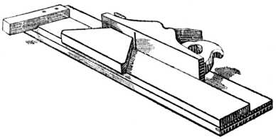
Sawing Block.—For sawing mouldings, etc., to their approximate shape, a home-made sawing block is generally used, as shown at Fig. 324. Two pieces of wood are glued one on the top of the other, the required angle is transferred thereto, and the saw kerf made. In the sketch the saw kerfs are shown at 45 degrees, right and left, and other angles and kerfs may be made where desired.
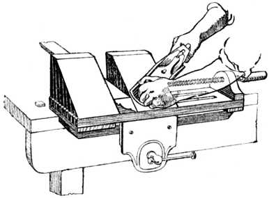
Planing.—After sawing the piece to approximately the correct angle, it is necessary on high-class work to plane the cut end so as to give a perfect finish and enable a glued joint to be made. This may be accomplished by using the plane on the shooting board, as shown at Fig. 325, and, if the worker is constantly using mitres of various angles, it is an easy matter to make new angle blocks and fix them on to the board. Other workers prefer the screw mitre trap shown at Fig. 326. This apparatus takes wide plinth or cornice moulds, and the angle may be altered by fitting temporary packing pieces under the work so as to tilt the moulding to the desired angle. The method of using the plane is indicated in the illustration.
Another method in everyday use by those workers who are constantly mitreing wide pieces of stock at 45 degrees is the “donkey’s ear” shooting board illustrated at Fig. 327. The plane is laid on its side on the surface of the board marked A, and used in a similar manner to that shown at Fig. 325.
A simple method and one that should always be remembered because it is handy when working without a shooting board is shown at Fig. 328. Set the marking or cutting gauge to the thickness of the wood to be mitred at 45 degrees; then gauge this distance on the wood, as shown at B; draw from the line to the edge, as shown, and saw and plane to a finish. The diagonals of a square give 45 degrees, and this is the method used to mark out the work. The end of the wood must, of course, be square with its edges before marking out in this manner.
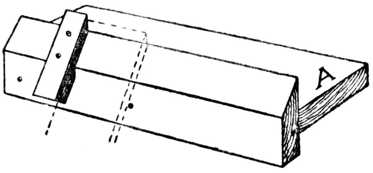
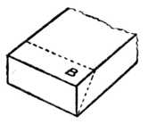
Fig. 328.—Gauging for Mitres. |
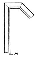
Fig. 329.—Narrow Inner Moulding. |
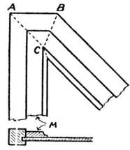
Fig. 330.—Wide Mitred Moulding. |
Fig. 329 shows a bevelled framing into which has been mitred a narrow moulding M so as to show a correct margin around the panel.
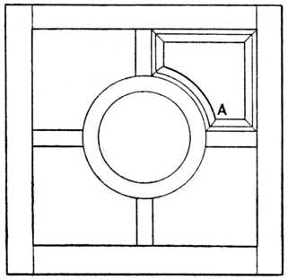
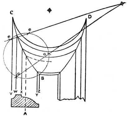
Fig. 330 shows a similar framing, but with a wide moulding M mitred around it. To obtain a correct intersection of this moulding, the angles A and B are bisected. The bisection of the angles meets before the width of the moulding is cleared, therefore the angle C will again have to be bisected, and the finished joint will appear as shown. One of the simplest of mouldings with a large flat face has been chosen to illustrate this. The moulding could be all in one width, as shown, or it could be built into the framing in separate pieces, the wide flat and the piece carrying the mould.
Curved Mitres.—We now come to what are probably the most difficult of all mitres, viz., curved mitres, and the writer well remembers in his apprenticeship days his first experience of attempting to fit the mouldings around the door shown at Fig. 331 by using straight mitres at A. This, of course, is impossible if the mouldings are of the same section and it is desired to make all the members correctly intersect. If straight mitres are used the section of the curved moulding will have to be of a different shape from the section of the straight moulding, and in these days of machine-made mouldings this method is seldom resorted to. It is better, cheaper, and easier to make curved mitres when the necessary machinery is at hand.
To Set out a Curved Mitre (see Fig. 332).—Draw a section of the moulding full size, A, as shown at the left hand of the illustration, and project lines round the framing, as shown V, W, X, Y and Z. Where the lines V, W, X, Y and Z intersect at the corner D, it clearly shows that a straight mitre will not cut all the points of intersection. A curved line will cut all the intersections, and a template made of cardboard, sheet zinc, or veneer, should be made to this shape. At the left-hand side the geometrical setting out is shown for obtaining the curve without having to resort to drawing it freehand.
Take half the width of the moulding, as shown by dotted line A, and where it cuts the approximation of the curved mitre place the point of the compasses and strike out a circle as shown; with the same radius place the compass point on B—that is, the inside point of the mitre, and cut the circle on the right and left with the small arcs shown at aa. With the same radius put the compass point at the junction of the circle and mitre line, C V, and cut the circle at right and left, viz., ee.
Now rule a line through aa, and another line through ee, and where these lines cut each other it will give the correct radius of the curved mitre. The advantage of knowing the correct radius of a curved mitre is of great benefit to the skilled machinist, as it enables him to set up his machine so as to give a definite result.
Mitreing a Moulded Door Frame.—Fig. 333 illustrates the method of mitreing the moulded portion of a door frame where the joint is dowelled, not tenoned. A small wooden template is made out of beech or other hardwood, having its ends cut at 45 degrees. This template is placed on the rail, as shown, and held in position by placing both the rail and the template in the vice. The face of the template forms a guide for a wide chisel, and enables the worker to gradually pare away the moulding to the correct angle.
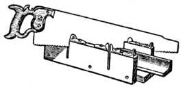
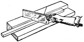
For sawing the mitres on large mouldings such as are used on the lid of a gramophone or wireless cabinet, a mitre sawing box and a panel saw may be used as indicated at Fig. 334.
<< BACK | INDEX: Woodwork Joints by William Fairham | NEXT >>