The tongued and grooved joint is used in one form or another throughout the whole of the woodworking trades, covering, as it does, a great variety of work from the laying of flooring boards to the construction of dressers, bookcases and other cabinet work.
Flooring and match boarding generally have the tongues worked on the solid board, and examples of a few of the various types are shown as follows:—
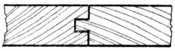
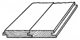
Fig. 94. |
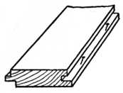
Fig. 95. |
Method of Nailing Hardwood Floors.
Fig. 93 shows the end view of the ordinary 7⁄8-in. “Tongued and Grooved Flooring board,” as used in the construction of floors for mills, workshops and cottage property. This type of flooring is nailed to the joists in the ordinary manner, no attempt being made to conceal the nails used.
Fig. 94 is a section of flooring which is generally made of hardwood, such as maple, oak, or jarrah. It is used in positions such as ballroom and skating rink floors, etc., the tongue and groove being worked in such a manner that the joint covers the nails as shown. Each nail is driven into its position at one edge of the board, the groove holding the next board and hiding the nail (Fig. 95).
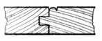
Fig. 96.—Tongued and Grooved Matchboarding, with Bead on One Side. |
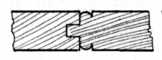
Fig. 97.—Tongued and Grooved Matchboarding, with Bead at Each Side. |
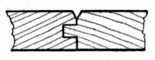
Fig. 98.—Matchboarding, Tongued, Grooved and Vee’d. |
Fig. 96 shows an example of matchboarding known as “Tongued, Grooved and Beaded” on one side only, and Fig. 97 shows a similar type tongued, grooved and beaded on both sides. This variety of matchboarding is known in the trade as “T. G. and B.” It is used for nailing on framing to form partitions for rooms, offices, etc., for panelling corridors, etc., and for making framed and ledged doors, building tool houses, cycle sheds and other outhouses.
Fig. 98 is an example of matchboarding that is tongued, grooved and vee’d on one side, and Fig. 99 shows tongued, grooved and vee’d both sides. These are used for similar purposes to Figs. 96 and 97, and many prefer the V matchboarding variety because it is more easily painted than the beaded variety.
The object of working a bead or beads on matchboarding is to break the jointing of the various pieces and to aim at ornamental effect; also to prevent unsightliness should the timber shrink slightly. When a moderate amount of shrinkage takes place, as is nearly always the case, the joint at the side of the bead appears to the casual observer to be the fillet or channel worked at the side of the bead. If the tongues are not painted before the work is put together, the shrinkage will cause the raw wood to show and thus make the joint too much in evidence.
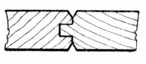
Fig. 99.—Matchboarding Vee’d Both Sides. |
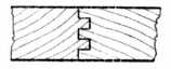
Fig. 100.—Double-tongued Matchboarding. |
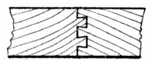
Fig. 101.—Double-dovetailed, Tongued and Grooved. |
Fig. 100 shows a “Double tongued and grooved” joint used in the wholesale cabinet factories. It is preferred for the jointing of cabinet stock, and the amateur can make a similar joint by working two grooves and inserting loose tongues.
Fig. 101 is the end view of a “Double-dovetailed, tongued and grooved” joint, and Fig. 102 is a sketch of a similar joint having only one dovetailed tongue.
From a constructional point of view Fig. 101 is far and away the best joint that has yet been produced. Unfortunately, however, there is not at the present time any hand tool that will economically produce it, owing probably to the fact that the joint is the subject of a patent. The dovetail tongue tapers slightly throughout its entire length, gripping the joint on the principle of the wedge and squeezing the glue into the pores of the wood.
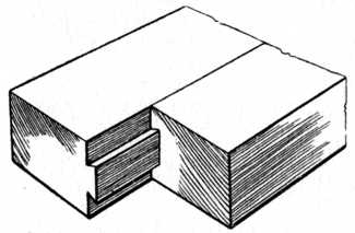
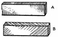
Fig. 103.—(A) Cross Tongue. (B) Feather Tongue. |
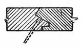
Fig. 104.—Method of Secret-nailing Hardwood Flooring Boards. |
Cabinet-work Joints.—With regard to tongued and grooved joints which apply more particularly to the jointing of cabinet work, Fig. 93 is produced by planes which are specially made for the purpose. One plane makes the tongue and another the groove. The handiest sizes to buy are those which joint 3⁄8 in., 5⁄8 in., and 3⁄4 in. timber, it being usual to dowel or loose-tongue thicker boards. The 3⁄8 in. partitions (or, as they are sometimes called, dustboards) between the drawers of a sideboard or dressing chest are in good work jointed in this manner. The 5⁄8 in. and 3⁄4 in. ends and tops of pine or American whitewood dressing tables, wardrobes, etc., call for the larger sized plane.
Loose Tongues.—There are two methods of jointing with loose tongues, viz., the use of the cross tongue, Fig. 103 A, and the use of the feather tongue, Fig. 103 B. Cross tongues are the stronger when glued in their position and can be used very much thinner than feather tongues. Feather tongues are cut diagonally across the grain as illustrated.
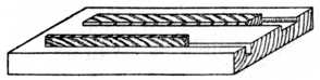
Fig. 105 is a cradle for planing up loose tongues to the required width (generally 7⁄8 in.). Two grooves are made in a piece of 11⁄4 in. hardwood; one groove is used for planing the width way of the tongue and the other for planing the edge way. These tongues can be cut to accurate size on a circular saw bench if power and machinery are at hand.
Applications of the Joint.—Fig. 106 is a sketch of a portion of a sideboard top, showing the plough groove ready worked out to receive the tongue; the other half of the top is treated in a similar manner. It will be noticed that the groove is not worked through the full length of the board, but stopped about 11⁄4 in. from each end; this leaves a square joint at each end of the top on which the moulding is worked. If the groove be run through the board it looks very unsightly when the mould is finished.
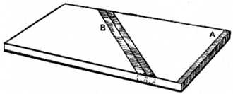
Fig. 107 is a shaped spandrel, such as is fixed in the recess of a sideboard or cupboard or shop window fitment. It is of such a width that, were it cut from a wide board, the shaped portion would be apt to break off owing to the short grain at C. The shaping is therefore built up out of three separate pieces, the grain running as indicated. The loose tongue is represented by the dotted line and a section is shown of the joint at the line A B. At the opposite corner the tongue is left blind, i.e., not run through the edge. This is the method that should be used when the shaping is above the level of the eye.
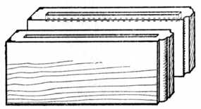
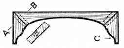
Fig. 108 shows part of a carcase of a dressing table. The drawer runner A is shown grooved across the end to receive a cross tongue; this cross tongue engages a similar groove in the front bearer. This method of fastening the runner to the bearer is in everyday use.
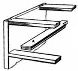
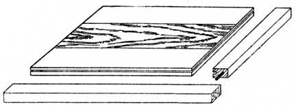
Fig. 109 is a writing table top. The centre boards are first jointed and glued up, after which the ends and sides are grooved ready to receive the cross tongues. The hardwood margins are shown at one end and at the front, and the grooves are arranged so that, on completion, the marginal frame stands above the top just the amount of the thickness of the leather which will cover the table. In some cases the margin at the end runs the same way of the grain as the top, thus allowing for slight shrinkage. Cross tongues would of course be used in this case.
Fig. 110 is a sketch showing one-quarter of a barred or tracery cabinet door. An enlarged section of the astragal mould which is grooved to fit on the bar which forms the rebate is also shown.
Fig. 111 is a “Combing or corner locking” joint, a method of making boxes by means of a continuous use of tongues and grooves instead of dovetails. This type of joint is generally machine made. The amateur, however, who is not proficient to undertake a dovetailed box frequently uses this method.
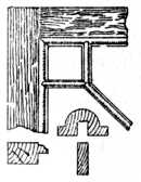
Fig. 110.—Corner of Barred Door. |
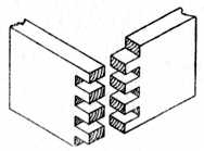
Fig. 111.—Combing or Locking Joint. |
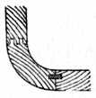
Fig. 112.—Single Loose Tongue and Double-tongue Joint. |
Corner Joints.—Fig. 112 shows both a single loose tongue and a double solid tongue. Both are methods used to connect circular cornered work, such as a counter end, to the front framing.
Fig. 113 indicates a tongued and grooved joint suitable for edge or end jointing, such as fitting matchboarding round a chimney breast, making small jewel drawers, etc.
Fig. 114 is a tongued and grooved joint with a bead worked on same to hide the joint, sometimes called a staff-bead. It would be used in positions such as boarding around an upright iron pillar, etc., the bead giving a neat finish at each corner.
Fig. 115 is a similar joint, but at an obtuse angle. An example of its use is in fixing boarding around an octagonal column of brickwork.
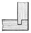
Fig. 113. |
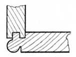
Fig. 114. |
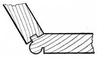
Fig. 115. |
Examples of Tongued and Grooved Corner Joints.
Fig. 116 shows a tongued and grooved mitre as used for strengthening the corners of cabinet work, such as tea caddies, small boxes, plinths, etc. Two pieces of wood are glued in position and allowed to set prior to glueing and cramping the joint proper. These pieces are afterwards planed away, thus leaving a clear surface to the box sides.
Fig. 117 shows the method of working the groove in the above joints. The pieces are turned back to back, the mitres thus making a right angle. The guide on the grooving plane thus works against each face of the joint, and this ensures correct jointing.
Fig. 118 is somewhat similar to Fig. 113, but with a quarter circle mould to hide the joint.
Fig. 119 indicates the building up of a double skirting mould. C represents the brickwork, A the oak-framed panelling, and B the packing and fixing block. A wide skirting of this type is made in two portions for convenience in working the moulding and to prevent undue shrinkage.
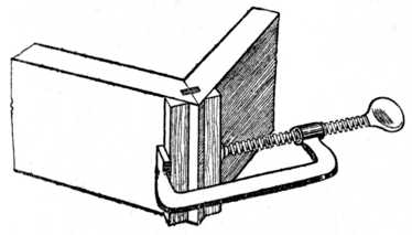
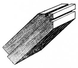
Fig. 117.—Working a Groove. |
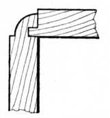
Fig. 118.—Corner Joint with Corner Mould. |
Fig. 120 illustrates the use of a tongued and grooved joint for fixing together the sides of a corner bracket, and the same method holds good when jointing a corner cupboard. A capping mould or top shelf will conceal the joint; it then has the appearance of a glued butt joint, but is of course considerably stronger. No screws or nails are required if this joint be used.
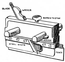
Ploughing.—When grooves have to be worked in the edge or face of a board to receive tongues, the process is generally called ploughing, and it is usually accomplished by a special tool called a plough (or, as it is occasionally spelt, “plow”). When a plough plane is bought it is usual to procure eight plough bits or blades of various sizes to fit the plane. In Fig. 121 is given the sketch of a plough plane with the names of the various parts lettered thereon.
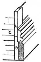
Fig. 119.—Double Skirting Mould. |
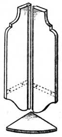
Fig. 120.—Joint for Corner Bracket or Cupboard. |
The board or boards which it is desired to groove are first planed straight and true, exactly as though it were desired to make a glued or butt joint. One of the boards is now placed edge way up in the vice and with the face side to the worker.
Take the plough plane and select a suitably-sized blade; fix it in the plane in the usual way, allowing the cutting edge to project beyond the steel skate about 1⁄32 in., and securely drive up the wedge. Next loosen the small boxwood wedges at the side of each stem, and adjust the plane by tapping the stems with a hammer until the cutting iron is in the desired position; then knock up the small wedges nice and tight. When setting the fence to or from the blade it is a wise precaution to measure the distance from the fence to the skate at each end of the plane; this will ensure the skate being parallel to the fence. The neglect of this is a source of annoyance to many amateurs. Now adjust the depth stop by turning the screw at the top of the plane, measuring the depth of the required groove from the edge of the blade to the stop, and carefully lock the screw which adjusts this stop.
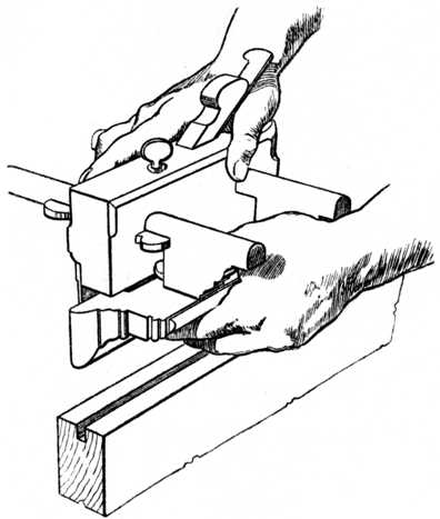
The plane is now ready for use. Hold the fence close up to the side of the timber, the hands in position as shown at Fig. 122, the position of the body being that generally assumed in planing. Move the plane backwards and forwards in the usual manner, beginning the cut at the end of the board nearest to the vice jaws (the front), and proceed with the planing until the depth stop is in contact with the wood. Then take a step backwards and repeat the process until the whole length of the groove is ploughed. Care must be taken to force the fence up to the board with the left hand, whilst the right hand thrusts the plane backwards and forwards, and the plane must be kept vertical.
Tongueing.—The grooves having been completed, the tongues have to be made. Fig. 123 shows a sketch of a board and the method of marking out cross tongues (A) and feather tongues (B). The usual procedure for making cross tongues is to plane the end of the board and use a cutting gauge to give a line the required distance from the end (see sketch). The board is sawn with a tenon or panel saw, and the piece of timber for the tongue is thus procured. If a feather tongue is to be used it is cut diagonally from the board (B) and the ends cut square as shown by the dotted line.
Feather tongues can be obtained in fairly long lengths out of narrow boards, whilst on the other hand cross tongues are limited by the width of the board. After cutting off the tongues, they require planing with nicety to fit the grooves, and the advantage of a grooved board (Fig. 105) will be appreciated. A glue spoon similar to a plumber’s ladle is generally used to pour the glue into the grooves, and it is customary to glue the tongue into one board first; after allowing this to set, the joint is completed in the usual manner.
Tongueing Planes.—Fig. 124 shows the end view of a tongueing plane for working matched joints out of the solid. The method of holding and using the plane is similar to the directions given for using the plough. The part lettered F (in front) represents the fence, which in this case is not adjustable.
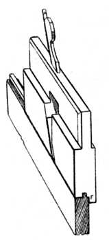
Fig. 124. |
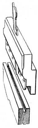
Fig. 125. |
End Views of Tongueing and Grooving Planes.
In description Fig. 125 is similar to Fig. 124. The steel skate runs in the groove and supports the cutting blade similar to that in the plough plane, and provided a grooving plane of this type is of suitable width it may be used for making grooves for loose tongues. There is on the market a metal plane which is specially designed with handles at both ends. This plane carries a grooving iron on one side and a tongueing iron on the other side; thus with one plane both the tongue and the groove can be worked.
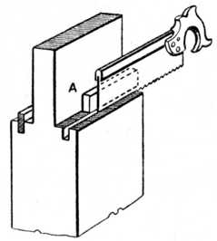
Fig. 126 shows the method of tongueing the shoulders of tenons as used in thick timber which is to be veneered on the face. A temporary piece of wood (A) is put between the tenon cheek and the saw, thus forming a guide for the latter. After cutting one saw kerf a thicker piece is made and a second saw kerf cut; the waste between the saw kerfs is now removed with an 1⁄8 in. chisel and this completes the groove. A tongue of this type acts as an extra tenon and prevents the joint from “lipping” (becoming uneven) on the face side.
<< BACK | INDEX: Woodwork Joints by William Fairham | NEXT >>